Particles that are transparent to the beam are not of concern here. This leaves only attenuation elements – those elements that cause a loss of photons from the beam regardless of the cause of loss.
Recall that the laser transmits a constant number of photons per second; the receiver converts the number of returning photon per second into a proportional number of charges per second which is equivalent to electrical current.
Not only is the optical path volume dependent on path length z, the number of attenuation elements along the path is also distance and temperature-dependent (and other factors not of concern here).
Only a consideration of the absorption elements is required since the effect of scattering elements is eliminated in the differential measurement. (Scattering elements affect compliance range, not differential ratios … in this ideal examination)
Partial pressures and density are of significant interest in the measure of atmospheric gases.
Atmospheric Carbon Dioxide (CO2)
This discussion of atmosphere is based on the idealized Standard Atmosphere Model parameters. Adding physical variations to this ideal representation will not decrease the uncertainty of measurement. Both density and temperature are of interest.
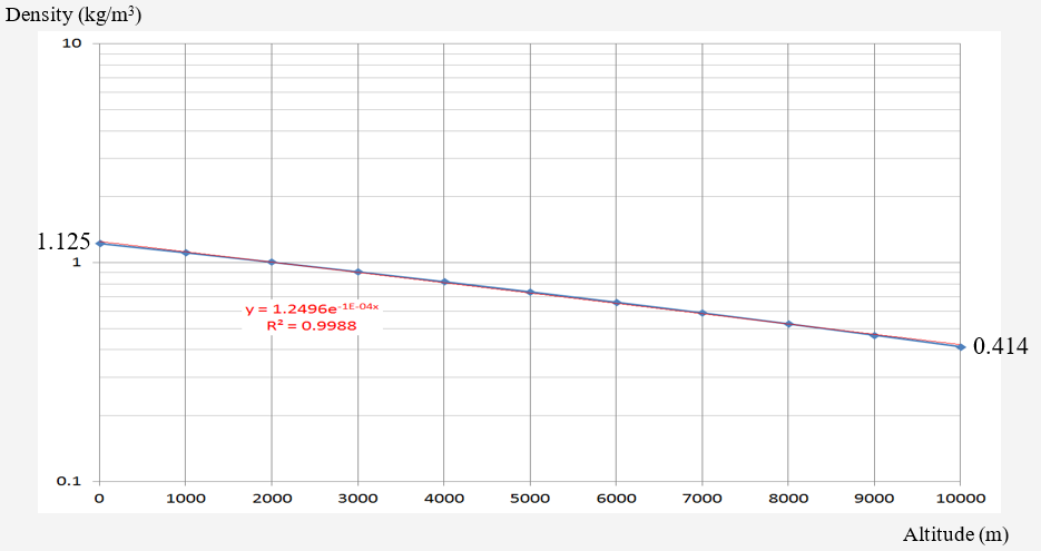
According to data from the Standard Atmosphere model, the atmospheric density for altitude up to 10 km is plotted below. The (almost) linear (log) relationship still holds (R = 0.9988)
*en.wikipedia.org/wiki/U.S._Standard_Atmosphere – leads to additional references
Standard Atmosphere Density Model

The trend line expression (R2 = 0.9988) for dry atmospheric density is
![]()
The density decreases with altitude as:
1) atmospheric density at sea level: 1.125 kg/m3 ;
2) atmospheric density at 10 km: 0.414 kg/m3
The ratio of decrease is compared with an attenuation factor of 1/e
![]()
This suggests that 10 km represents the “atmospheric pressure altitude constant”: i.e., at 20 km, the pressure would decrease by a factor of e -2 (0.13) – atmospheric pressure is 13% of sea-level at 11 km.
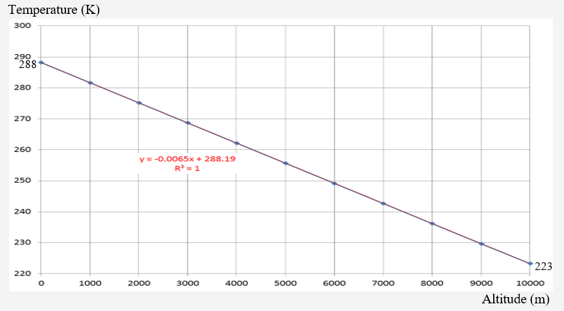
The Standard Atmosphere temperature profile up to 10 km is given as:

The trend line expression (R2 = 1.0) is
![]()
An R2 value of 1.0 raises a degree of wonderment about the data but it is known actual temperature varies in both initial value, slope, and monoticity.
This plot represents a “standard” temperature profile; both temperature slope and initial temperature are highly variable over even short periods of time, day, season. As this is not a direct discussion of atmospheric science but rather a determination of the limits of measurement, suffice to suggest that even this benign temperature variation has significant effects on measurement uncertainty; temperature variations will affect the measured data and its interpretation; moisture content even more so.
Species of Interest: Atmospheric CO2 , O2 , H2O
The measure of CO2 is assumed to be of common interest. A few bits of auxiliary information about CO2 in the atmosphere will aid in filling some knowledge gaps for this experiment parameter estimation. Knowledge of O2 is also useful in extracting CO2 information from the measurement. Water vapour has a significant influence on the measurement environment.
Nominal CO2 is uniformly distributed by volume percentage throughout the atmosphere. Although a topic of controversy, the distribution is in the neighborhood of 400 ppmv (0.04% of the atmosphere). Assume a desire to measure CO2 concentration to 1 ppmv : the system needs to resolve 1 part of 400; approximately 0.25% (1:400) of 0.04%.
Both CO2 and O2 have an ideally uniform mixing ratio to the altitudes of interest herein (about 10 km)

Since CO2 has a (nominal) uniform distribution in the atmosphere, it is the deviation from the nominal value that is of interest. An increase in CO2 will increase absorption of the ON beam causing a decrease in intensity. The intensity of the OFF wavelength will not be affected by CO2 [1]
In this measurement scheme, the wavelengths of the two beams are subject to identical transmission path factors such as scattering and reflection coefficient. If the environment is constant – no changes in CO2 concentration – the ratio of absorption to non-absorption is also constant. If the ratio changes, it may be assumed a change in CO2 concentration within the measurement column changed the amount of absorption.
The measurement goal is to detect deviations in concentration to 1 part in 400 … 0.25% or 4 parts per thousand. A 10-bit ADC has a resolution of 1 part per 1024; to allow for perturbations in the instrument, measurement accuracy suitable for an ideal conversion in a 12-bit ADC (1 part per 4096) will be the design goal. What is needed is an estimate of the expected magnitude ranges and error bounds.
[1] As implemented, the OFF channels are actually selected to be on the edge of the absorption band of CO2. The response ratio may be used as an indicator without significantly changing the wavelength/size relationship with scattering agents. For purposes of explanation within this document, independence of response will be assumed. The differences in details are scaling factors
Vertical CO2 Mixing Ratio
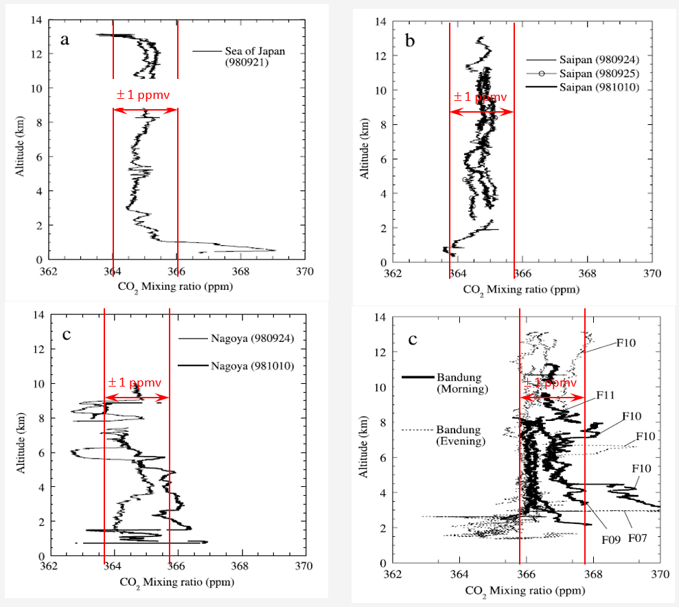
The percent density of CO2 in the atmosphere is fairly constant with altitude. The following figures[1] are based on physical sampling; representative illustrations of expected vertical variation in atmospheric CO2 provide a feeling for the variations possibly to be expected in this measurement.
Figure 3 of the referenced source shows 3 sets of empirical data (upper 2 and lower left) from different locations:

The plot in the lower right is from Figure 4 in the reference showing 12 profiles over the same location.
“The differences in CO2 mixing ratio at the lower altitudes were likely created by diurnal changes in activities in the land biosphere around Bandung [2]”
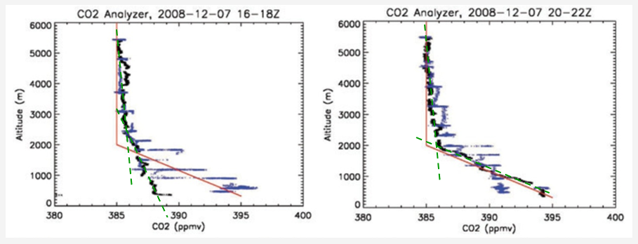
Additional physical measurement of concentration vs. altitude comes from within NASA. Dr Albright of NASA’s Goddard Space Flight Center published [3] the following charts showing the concentration profile based on data collected from an infrared gas analyzer.

Based on aircraft-based infrared gas analyzer
It is assumed the altitude is absolute-above-sea-level; there is no discussion about topography adjustments
This data suggests a strong concentration variation below about 2 km with relatively constant concentration at higher altitudes. The probability of absorption increases at lower altitudes although the specific measurement in the experiment of interest does not differentiate altitude dependencies.
The combined information from these two experiments suggests the improbability of obtaining the desired accuracy of concentration from remote sensing techniques of this type. I question the curve-fitting (RED) in the left-hand figure;
I suggest the GRN lines are more representative of the data – however, there is a distinct break at about 2 km – 6562 ft. (this introduces a question regarding location; how would the data over the USGS Denver office appear – about 5800 ft; 1770 m)
[1] Machida, T, Kita, K, et al, “Vertical and meridional distributions of the atmospheric CO2 mixing ratio between northern midlatitudes and southern subtropics”, J. Geophys. Res., 107, 2003
[2] Ibid
[3] Abshire, et al, “Pulsed airborne lidar measurements of atmospheric CO2 column absorption”
That’s all for now. Next 6: Absorption Cross-Section
Back 4: Absorption Parameters
Up: Articles
