When configuring systems for multi-phase clocking – be it bi-phase for basic switched capacitor networks or many phases for sophisticated signal processing, it is often desirable for the clock phases to not overlap. As clock speeds increase, the rise and fall times of the individual phases need to squeeze within the “dead-time” allowed. Rise time being associated with bandwidth, the platform material may become a factor.
The inspiration for this discussion came about from an 8-phase clocking scheme developed for some prototype ADCs I once worked on. Getting the clocking scheme working as both desired and necessary turned out to be one of the more complex challenges of the project – everything works so well in the simulation universe – hence the discussion on rise times and non-overlap … keeping in mind that fall times are actually often slower than rise times.
I hope you enjoy the articles …
-
Clock Edges: Part 1 Introduction
In many mixed-mode circuits, various circuit functions may be controlled by multi-phase clocking. In many – if not most – cases, it is desirable for these clocks to be non-over-lapping – a “break-before-make” switch function. Clock pulses are often more rectangular (trapezoidal) than “square”; one primary difference is that ideal square waves contain no even…
-
Clock Edges: Part 2 Harmonics
So, what to do, what to do … Let’s consider a system built on a printed circuit board (PCB). The most common PCB material is FR41 which has a corner frequency of around 1 GHz or so. The actual bandwidth of FR4 varies depending on specific material, thickness, trace width, # layers, and other such.…
-
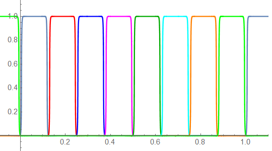
Clock Edges: Part 3 Non-Overlapping Clocks
The advent of multi-phase signal processing places greater constraints on what constitutes acceptable clocking criteria. The simplest case is a bi-phase clock. One basic application of a bi-phase clock is controlled charge transfer using switched capacitors. Such a circuit could appear as: phi1 and phi 2 are opposite phases. When phi1 is H, phi2 is…
-
Clock Edges Appendix
The Fourier Series for a finite sum may be defined as: where The coefficients are found to be: For an amplitude-offset square wave, the function may be defined: where where and which gives: Consider a pulse sequence of amplitude A and duty-cycle d…