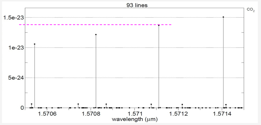
The effective absorption cross-section of the species of interest: CO2 is very highly dependent on wavelength as shown in the following figures.
Carbon Dioxide alone
Including major atmospheric gas constituents: the only significant gas in this vicinity is carbon monoxide.
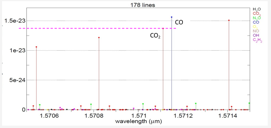
Among the primary atmospheric gases of interest, only CO2 and CO have significant spectral responses[1] near the wavelength of transmission (among H20, CO2, N2O, CO, O2, NO, OH, C2H2) The presence of water should not introduce significant absorption.
Oxygen (O2) is suggested as a reference gas
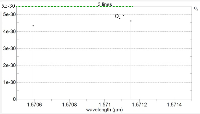
As a reference indicator, O2 is measured near 1261.8 nm
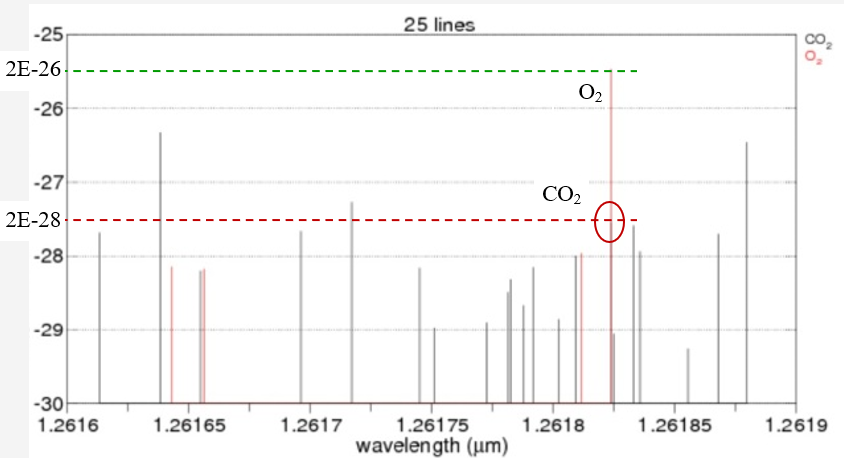
There is a relatively significant CO2 response line at this wavelength as well. Although a comparison measure of O2 to reference CO2 is ideally viable, the measurement of O2 is subject to the same geometrical considerations as CO2 with the complexity of a substantially lower signal level. The measure of O2 would need considerably less uncertainty than the measure of CO2 to obtain an accurate measure of CO2 concentration.
The dynamic range of optical intensity at this wavelength introduces additional concerns in the receiver development portion of this exercise as well.
[1] Data based on HITRAN2008 via SpectralCalc (GATS, Inc)
Recalling the original formulation:

Assuming molecular absorption cross-sectional area ![]() to be constant but number of absorbing molecules to be a function of both distance z and temperature T
to be constant but number of absorbing molecules to be a function of both distance z and temperature T

The function is different for a vertical column than a horizontal column due to the dependence of density on altitude.
Recalling units:

Using US Standard Atmosphere parameters:
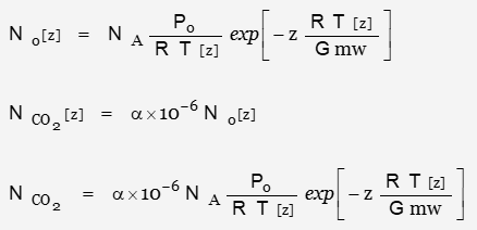
Number of atoms per unit volume as function of altitude

The mixing ratio is assumed independent of altitude; the number of CO2 molecules per unit volume is:
![]()
Defining ![]() as a parameter describing the value of the proportion of CO2 in the atmosphere:
as a parameter describing the value of the proportion of CO2 in the atmosphere:
![]()
in units of molecules per unit volume.
The value of parameter ![]() is the focus of the desired measurement.
is the focus of the desired measurement.
The number of molecules within the optical path is not only a function of altitude, but of the geometry of the path itself. Roughly conical in shape, the shape of the transmitted path is different than that of the path of reflection.
Since each absorbing molecule is assumed available for interaction with photons travelling both paths
![]()
in units of absolute number of molecules.
As a function of distance, the volume of the optical path is defined as:

where A[z] is the beam cross-sectional area[1] as a function of z.
Specifically:

The volume of the reflected optical path is defined as:

where Heff is the effective length of a truncated cone between the terminal planes
![]()
[Side note: Re-arranging the volume expressions … ]

[1] The beam projection is normal to the reflecting surface and symmetrical around the axis
Expanding the initial expression for optical depth and defining the path length zero at the instrument:
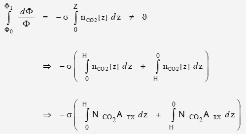
where total path length Z is twice the altitude H of the measurement platform above the reflector.
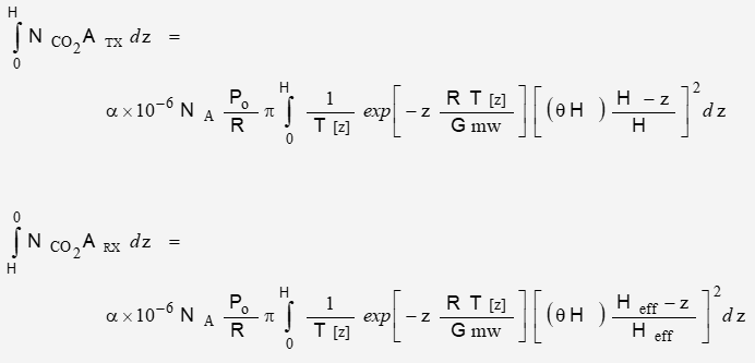
The expression is derived from:
With substitutions:
Effective Absorption Cross-Section
CO2 spectral data:

Optical depth is the distance at which ![]()
a z where a is the total result of all individual attenuation factors – split into “absorbed” and “scattered”.
Since s is assumed a constant derived from the total effect. Individual scattering attenuation factors may vary
The individual species ni which consist of dry air may not scatter (only one species will absorb). Only the scatter and absorb attenuation factors appear but the densities of those factors may not total the dry air total.
where dry air density is
where of all elements of dry air density total 24.98e18 molecules/m3
Parameter ppmv defines the CO2 density; it remains to allocate scattering coefficients. ppmv is linear with respect to ndry to above the altitude of interest
na = ppmv ´ ndry
ndry = ns + nn + (ppmv ´ ndry)
na only accounts for ppmv of the total. From an analysis point of view, the scattering allocation can range from 0 to (1 – ppmv). Since the desired resolution is 1ppmv, the percentage of scattering agents within the total atmosphere will have a significant effect on signal detectability.
It has been suggested that a scattering coefficient of 10e-5/m for IR wavelengths in the 1 – 2 um band. It is also stated that the scattering cross-section is much smaller than the absorption cross-section such that scattering may be neglected … except for factors on the order of the size of water droplets or ice crystals.
The van Waals diameter for CO2 is about 250 pm with related area of 49.09e-21 m2.
Determination of J and sa
The basic Beer-Lambert expression may be stated as:
which for the situation at hand is
There are three classes of atmospheric constituents: scatterers, absorbers, and neutral. Most are neutral; they have no effect on photons. The absorbers are those molecules sensitve to the particular wavelength – CO2 at about 1571 nm herein. Everything else is a scatterer; anything except absorption that causes a loss of a photon.
It has been estimated that the attenuation of the IR band between 1 and 2 mm is 10 ´ 10-5 Np/m. Altitude z being 10 km,
It has also been estimated that 1 of 10 million photons are received from 10 km altitude. For a source magnitude of 1, the system expression may be written as
Where R is primarily the surface albedo and diffusion but also includes other linear losses such as those in the optics, filters, and inexact alignment of beam to detector.
Common geophysical reflection coefficients for common surface materials may range from 0.1 to 0.95. For this estimation, R will be 0.2.
The expression is now:
Using the average value of the three callated densities
ravg = 10.3088e21 molecule/m3
The optical depth is now estimated as
For the variations of density previously calculated
J vs ppmv
power at telescope vs ppmv at R = 0.2
Received power for R = 0.1 – 0.9 and ppmv = 350 – 450
The maximum power is dry model, R = 1 and ppmv = 380
Ptele,max = 1.347 mW
The minimum power is ideal gas model, R = 0.1 and ppmv = 420
Ptele,max = 15.30 nW
The target design criteria for the receiver minimum usable signal is 1 nW (although the practical limit appears to be closer to 100 pW) so design for a minimum signal of 10 nW will increase SNR.
The minimum calculated signal is 15.30 nW, above the system design of 10 nW as the minimum signal. The largest calculated signal is 1.35 uW; the system design will use 5 uW as the maximum signal magnitude.
The signal dynamic range is:
That’s all for now.
Next 7: Plots
Back 5: Atmospheric Carbon Dioxide
Up: Articles
