All plots use parameters as listed unless noted [1]:
![]() CO2 = 380
CO2 = 380 ![]() CO2 = 1.4e-23 HCO2 = 5552
CO2 = 1.4e-23 HCO2 = 5552
To = 288.15 T[z] = To – 650e-6 z
H is altitude (10 km) ; z is length of total path: z = 2 h
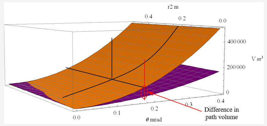
1) Optical path volume dependency: beam divergence ![]() ; lens radius r2 for fixed H = 10 km
; lens radius r2 for fixed H = 10 km
TX volume is PUR ; RX volume in ORG.
Experimental value is ![]() = 0.17 mrad; r2 = 0.1 m
= 0.17 mrad; r2 = 0.1 m

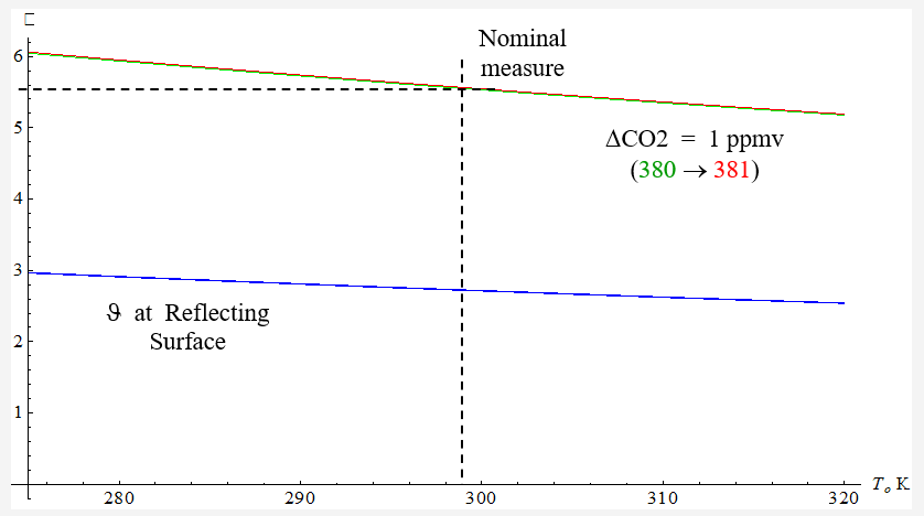
2) Optical depth over h (altitude) and nominal surface temperature.
Transmitter path is BLU;
RED is optical depth for TX at reflecting surface;
GRN is along RX path

3) The instrument only “sees” the signal at the end of the RX travel path
The optical depth vs surface temperature: BLU at reflecting surface; GRN at receiver (measured)

with DCO2 of 1 ppmv Referenced to Nominal
The GRN line represents a measurement at nominal CO2 concentration (380 ppmv); the RED line represents an increase in CO2 concentration of 1 ppmv (the desired measurement resolution)
Note that this is based on a temperature profile based on variation in surface temperature with no change in slope dependency in z
4) From: ![]() =
= ![]() o exp [-
o exp [-![]() ] where
] where ![]() o = 1
o = 1

In this ideal case – and if temperature were constant – this difference could be detected.
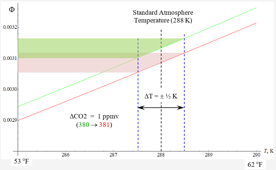
5) Detail of Figure 4

GRN 380 ; RED 381
A variation of ±½K (~ 1°F) causes variation in received signal strength highlighted by colored polygons.
6) Normalized receive signal ![]() from
from ![]() = exp [-
= exp [-![]() ] for variation
] for variation

GRN: Nominal
 ; RED:
  + 1 ; BLU:
  + 10
+ 10These plots represent the differential ratio; not absolute common-mode signal strength.
[1] Physical constants obtained from NIST ; spectral parameters derived from HITRAN2004/2008
That’s all for now.
Next 8: Basic Reflectivity & Range
Back 6: Attenuation Elements
Up: Articles
