The magnetic moment M of a circular coil is determined from the surface area enclosed by the coil, the current flowing through the coil, and the number of turns in the coil. The current variable ![]() in the following development will be understood to be equivalent to
in the following development will be understood to be equivalent to ![]() .
.
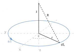
Define a differential length segment dL along the coil.
![]()
Distance R from the coil to some point along the z-axis is:
![]()
Taking the cross product:

The symmetry of the coil causes the ![]() terms to cancel; only the
terms to cancel; only the ![]() elements need be considered.
elements need be considered.
The Biot-Savart Law states ![]() where:
where:

in units of Teslas
The expression for the magnetic field along the z-axis becomes:
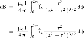
The field is symmetrical about the z-axis so that:
![]()
Since ![]() is simply the circular circumference:
is simply the circular circumference:
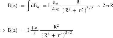
where ![]() is the coil radius and
is the coil radius and ![]() is the z-axis displacement of measurement off the coil plane.
is the z-axis displacement of measurement off the coil plane. ![]() is the number of turns in the coil, and
is the number of turns in the coil, and ![]() is the current through the coil. The magnetic field has units of
is the current through the coil. The magnetic field has units of ![]()
The field experiments used a 1 m coil of AWG10 wire. The coil has 30 turns and carries 30 A. The generated magnetic field of such a coil may be estimated by using the ideal expressions:
![]()
The ideal coil assumes a conductor of zero-diameter; the physical coil not only has a conductor of non-zero diameter, but the diameter of a multi-turn coil also has a diameter. The inductance of the finite coil may be estimated from![]()
![Rendered by QuickLaTeX.com \begin{displaymath} L \; = \; \mu_o \, n^2 \, a \, \left[ \, ln\left(\, 1 \, + \, \pi \, \frac{a}{b} \, \right) \; + \; \dfrac{1}{2.3 \, + \, 1.6 \, \frac{\, b \, }{a} \, + \, 0.44 \, \left(\frac{b}{a}\right)^2 \, } \, \right] \end{displaymath}](https://davemcglone.com/wp-content/ql-cache/quicklatex.com-1c44b9d7a0262e92fa5a7139e1b90168_l3.png)
where parameter ![]() is the diameter of the wire; parameter
is the diameter of the wire; parameter ![]() is the diameter of the wire bundle. The test coil inductance worked out to be about 52 μH.
is the diameter of the wire bundle. The test coil inductance worked out to be about 52 μH.
For subsurface exploration, the assumption is made that the distance from the coil to the measurement point is much greater than the coil diameter. I need to define a vector magnetic potential ![]() .
.
![]()
where ![]() is the distance from the coil to the measurement point … (and
is the distance from the coil to the measurement point … (and ![]() ). The system is symmetrical about z, the field is independent of the angle
). The system is symmetrical about z, the field is independent of the angle ![]() . The magnetic potential
. The magnetic potential ![]() is analogous to the electrical potential, aka voltage.
is analogous to the electrical potential, aka voltage.
It can be shown that:
![]()
where ![]() is the angular displacement off the z-axis. For measurements along the surface,
is the angular displacement off the z-axis. For measurements along the surface, ![]() where
where ![]() .
.
The expression for ![]() can be re-arranged:
can be re-arranged:
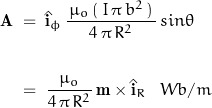
where:
![]()
where m is the magnetic dipole moment.
For the physical coil defined above, the associated magnetic moment is determined to be:
![]()
with the vertical component of the magnetic field on the surface being:

If the detection instrument is capable of resolving 0.05 nT, the ideal surface range of measurement is shown in this plot of field in teslas vs distance in meters.
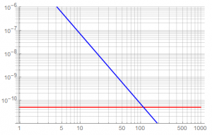
The lower limit of detection is shown in RED. The apparent detection range is about 100 m but this model assumes a free-space environment – real field conditions will greatly reduce this range … unless the source dipole is increased.
A resolution capability of 0.05 nT is equivalent to 500 nGs. The earth’s field ranges between about 30 → 65 μT … or about 0.3 → 0.65 Gs.
Development of an instrument for such measurements is a different topic.
That’s good for now.
![]()