To this point, several equations and idealized situations have been discussed without addressing the core question![]() : “How deep will it see?”. By presenting the theoretical considerations, some degree of confident expectation in anomaly detection in the ideal world is made.
: “How deep will it see?”. By presenting the theoretical considerations, some degree of confident expectation in anomaly detection in the ideal world is made.
The limits of exploration are defined by the capability of the measurement device to resolve a signal created by some target at sufficient strength to detect. A theoretical analysis, while considering significant issues concerning signal attenuation, rarely takes into account losses due to somewhat random and extraneous factors such as geological noise. Or assumptions that aren’t quite correct …
The shallowest depth that can be investigated is primarily limited by the sample time of the measurement system. The maximum depth may be defined as the point where the signal level falls to that of the background noise (or some other criterion of minimum-detectable signal). The determination of the maximum depth of detection answers the common question, “How deep can the receiver see?” but the answer is rarely as simple as the question. Ultimately, the only receiver parameter affecting the answer to this question is the resolution of detection which may be assumed – nay, not “assumed”; it ![]() independent of material parameters.
independent of material parameters.
The subsurface geophysical phenomena of interest in this discussion is conductivity contrast; magnetic field methods are best suited for seeking conductive regions. A method employed to determine this contrast requires the creation of charge movement within a conductivity contrast region strong enough to generate a detectable magnetic field at the surface.
During the course of this discussion, the primary field source has been a time-variant magnetic dipole used to create electromagnetic fields within some exploration volume of interest as defined by the surface area, XY, to some depth Z. X and Y are defined by the proposed exploration area; Z is typically taken to be some multiple of skin depth![]() – though skin depth is also a nebulous measure in terms of “How deep can it see?”
– though skin depth is also a nebulous measure in terms of “How deep can it see?”
Other source methods may be used: a long, current-carrying wire will generate a magnetic field around the wire; an electric field can be applied across a region to set up charge accumulation. The fundamental principle is to provide a controlled movement of charge to generate a magnetic field whose properties are dependent on a target’s dimensional and material parameters.
The wave equations described by Maxwell’s Equations have complex solutions to 2nd-order linear differential equations given as:

where ![]() is the attenuation factor and
is the attenuation factor and ![]() is the phase factor.
is the phase factor.
For a sinusoidal time stimulus and conduction current domination over displacement currents – as has been assumed throughout this discussion – the solutions are real and expressed as:
![]()
Which is actually over-simplistic for all but the most basic practical applications
The primary limitation on detectable signal strength is related to the skin-depth:

This factor defines the depth where the signal amplitude is reduced by a factor of ![]() : approximately 37%. However, the minimum detectable signal is determined by the receiver resolution and bandwidth as well as the background noise level. If a detectable signal derives from a source near or beyond a single skin depth, the analytic assumption of a far field needs to be reconsidered.
: approximately 37%. However, the minimum detectable signal is determined by the receiver resolution and bandwidth as well as the background noise level. If a detectable signal derives from a source near or beyond a single skin depth, the analytic assumption of a far field needs to be reconsidered.
In the time domain, the transient solution to an impulse stimulus leads to two functions of interest. At some distance ![]() from the dipole source along the z = 0 surface plane, the field reaches a peak value at:
from the dipole source along the z = 0 surface plane, the field reaches a peak value at:
![]()
Similarly, at some time ![]() , the field reaches a maximum value at a distance:
, the field reaches a maximum value at a distance:

With an impulse input and ![]() = 0.01:
= 0.01:
x = 50 m: the field reaches a maximum at t = 5 μs;
t = 10 μs: the field reaches a maximum at x = 40 m.
Typical values for background geologic noise range between 0.1 and 0.001 nT: the lowest useful resolution of a magnetic field receiver may be as high as 1 – 10 nT, depending on the region and detection goals. While the secondary fields of the examples presented in this discussion have magnitudes in the range of 0.1 – 10 nT, any measurement system will be expected to have the capability to extract this signal from any noise that may be present.
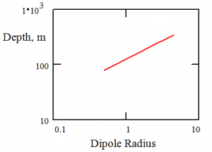
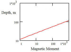
The source dipole has a significant effect on penetration depth. Taking into consideration the geological background noise, depth vs. dipole parameters for η = 0.01 nT are shown below. Variations of coil radius are shown in the first figure; variations of current moment N = n * i are shown in the second.


A 1 decade change (0.5 to 5 m) in radius changes the depth from about 90 to 500 m; a 3-decade change in magnetic moment (1 to 1000) changes the depth by about 1 decade – 10 to 100. A 5 m radius (~ 33 ft diamter) gets to be unwieldy; the magnetic moment is increased by increasing number of turns and/or the coil current. One of the field units used in prototype development had a 1 m radius with 30 turns of AWG10 wire carrying 30 amps. This can raise its own issues but one of the primary systems was successful in detecting shallow subsurface water, an unknown gold seam in the Sierra Nevada, and potential silver prospects in central Nevada.
At a frequency of 25 kHz and a conductivity of 0.2 mS (dolomite), the skin depth is 225 m. However, this limit may be overly simplistic: Of greater importance is the ability to detect the target anomaly. The primary field needs sufficient amplitude to create a perturbation in the target with sufficient strength to permit detection at the point of measurement. That depth may be considerably shallower than the skin depth – it may be deeper.
These exploration depth limits were calculated for a signal-to-noise ratio![]() (SNR) of 0dB, however, a more realistic estimate is for a minimum SNR of 3 dB – (and I prefer 20 dB) – unless special source stimuli and/or acquisition techniques are used. In many cases, the acquisition equipment will limit measurements in the time-domain for a shallow target, and dispersion attenuation will limit signal acquisition for deep targets.
(SNR) of 0dB, however, a more realistic estimate is for a minimum SNR of 3 dB – (and I prefer 20 dB) – unless special source stimuli and/or acquisition techniques are used. In many cases, the acquisition equipment will limit measurements in the time-domain for a shallow target, and dispersion attenuation will limit signal acquisition for deep targets.
So far, so good, and …
That’s good for now.
![]()