Magnetic Field
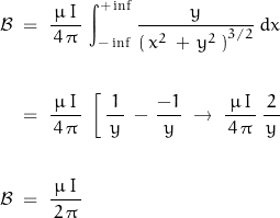
As usual, assume an infinitely long straight wire. The fundamental expression is the Biot-Savart Law
![]()
The system is symmetrical in both Cartesian and cylindrical coordinates; in Cartesian coordinates:

Or … using Amperes Law:
Assume a circular conductor with current distribution symmetric about the axis. Note that the external magnetic field is not dependent on the internal current distribution.
![]()
![]()
The term with ![]() relates to displacement currents; it may be eliminated as good conductors don’t have significant displacement currents.
relates to displacement currents; it may be eliminated as good conductors don’t have significant displacement currents.
Therefore, in a wire with radius R:
![]()
![]()
For the magnetic field outside the wire, the same expression holds: the law states that the field is created by the current enclosed by any closed loop around the current. Letting ![]() be the radius for any loop for
be the radius for any loop for ![]() (the loop does not need to be circular – the math is easier though):
(the loop does not need to be circular – the math is easier though):
![]()
The magnetic field also exists within the wire. The wire is assumed to have a circular cross-section with uniform current density (where current density ![]() ). A small loop with radius
). A small loop with radius ![]() will have a smaller current density.
will have a smaller current density.
![]()
where ![]() is the wire radius and
is the wire radius and ![]() the distance from the center.
the distance from the center.![]() may have any value
may have any value ![]()
Skin Depth
Skin depth is a means of quantifying the effect of frequency dependent current distribution within a material. As frequency increases, the current density decreases exponentially towards the center.
![]()
where ![]() is current density at DC and
is current density at DC and ![]() is “skin depth”.
is “skin depth”.
This expression assumes a planar interface.
One skin depth is the depth from surface where the current density has been attenuated by a factor of 1/e (~0.36788). It should be kept in mind that there remains significant current density below 1![]() . It requires 3
. It requires 3![]() for the current density to fall to less than 5%; 5
for the current density to fall to less than 5%; 5![]() to fall below 1%.
to fall below 1%.
The imaginary term indicates a phase delay of 1 rad for every unit skin depth.
An electromagnetic wave propagates through a material and decays in a manner described by:
![]()
where ![]() is the attenuation factor,
is the attenuation factor, ![]() is the phase factor, and
is the phase factor, and ![]() and
and ![]() are the time and space propagation parameters (time t and space z)
are the time and space propagation parameters (time t and space z)
Noting that ![]() and that skin depth is inverse of the attenuation term
and that skin depth is inverse of the attenuation term ![]() , and expression for current density may be written:
, and expression for current density may be written:
![]()
The attenuation factor ![]() is defined as:
is defined as:
![Rendered by QuickLaTeX.com \begin{displaymath}\alpha \;\;=\;\; \frac{\, \omega\,\sqrt{\,\mu\,\epsilon\,}}{\sqrt{\,2\,}}\,{\left[\,\left( \, \sqrt{\,1\,+\,\left(\,\frac{\sigma}{\,\epsilon \, \omega \,}\right)^2\,}\,-\,1\,\right)\,\right]^{1/2}\;\;Np/m\end{displaymath}](https://davemcglone.com/wp-content/ql-cache/quicklatex.com-10375476930cad5dfc15e05f4c548569_l3.png)
![]()
A bit of an ugly expression to work with. Don’t worry – it gets worse.
One way to deal with it is to apply a series expansion to the inner term of ![]() . Or use something like Mathematica.
. Or use something like Mathematica.
Letting ![]() and using a series expansion to 5th order, this equation may be expressed as:
and using a series expansion to 5th order, this equation may be expressed as:
![Rendered by QuickLaTeX.com \begin{displaymath}\alpha \;\;=\;\; \frac{\, \omega\,\sqrt{\,\mu\,\epsilon\,}}{\sqrt{\,2\,}} \; \sqrt{\,\left[ \, x\,+\, \frac{1}{\,2\,}\frac{1}{\,x\,}}\,-\,\frac{1}{\,8\,}\,\frac{1}{x^3}\,+\,\frac{1}{\,16\,}\,\frac{1}{x^5}\,-1}\,\right]\,}\end{displaymath}](https://davemcglone.com/wp-content/ql-cache/quicklatex.com-811c4c700cf3d42a6cfa468746ec1903_l3.png)
or:
![Rendered by QuickLaTeX.com \begin{displaymath}\alpha \;\;=\;\; \frac{\, \omega\,\sqrt{\,\mu\,\epsilon\,}}{\sqrt{\,2\,}} \; \sqrt{\,\left[ \, \frac{\sigma}{\,\omega\,\epsilon\,}\,+\, \frac{1}{\,2\,}\frac{1}{\,\frac{\sigma}{\,\omega\,\epsilon\,}}\,-\,\frac{1}{\,8\,}\,\frac{1}{\left(\frac{\sigma}{\,\omega\,\epsilon\,}}\right)^3}\,+\, ...\,-1}\,\right]\,}\end{displaymath}](https://davemcglone.com/wp-content/ql-cache/quicklatex.com-d0ad49a123ea406efb538344b58a7559_l3.png)
Or just simplify it …
Only the first term ![]() in the series is significant for conductive materials:
in the series is significant for conductive materials:
For copper: x = 10712 at 100THz; 10.7e15 at 100 Hz
![]()
Therefore, ![]() is approximated by:
is approximated by:
![]()
which happens to be close enough to the “exact” value (in good conductors) to only be of concern to those who seek “exact” values.
Even more straightforward, the term ![]() is 10,000 compared to 1 at 100THz and gets larger at lower frequencies. We’re in a different ballgame if this term is significant for purposes herein.
is 10,000 compared to 1 at 100THz and gets larger at lower frequencies. We’re in a different ballgame if this term is significant for purposes herein.

Just because I’m curious this way – what is the error?

The error exceeds 0.01% above 42.8 GHz. At that frequency, there are other factors that need to be accounted for.
As they say, “close enough for government work“.
This approximation is also identical to the expression for the phase component ![]() – again, in good conductors.
– again, in good conductors.
![]()
Inverting ![]() gives:
gives:

where ρ, resistivity, is equal to the inverse of conductivity σ and relative permeability is equal to 1.
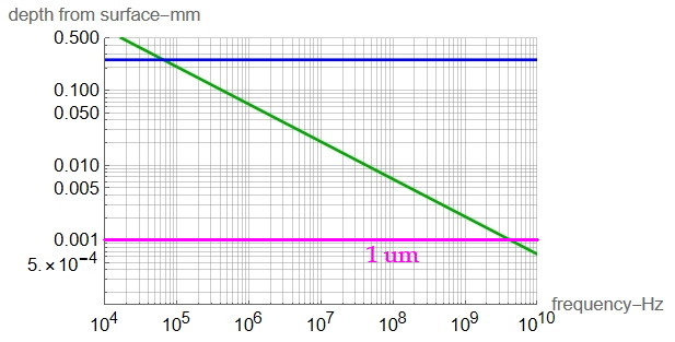
The diameter of AWG24 wire is 0.5106 mm. Applying this expression for copper over frequency gives:

Skin depth is less than the wire radius above about 65kHz.
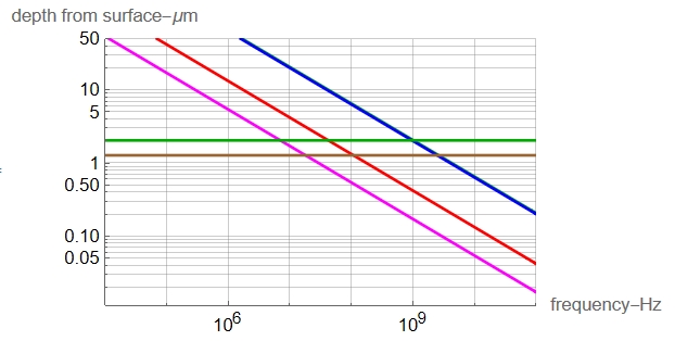
Plotting the expression for skin-depths of copper, silver, and nickel:

The diagonal traces are the skin depths for copper, silver, and two for nickel. Even though copper and silver have conductivities that differ by a few percent, nickel’s conductivity is much less and has a high relative permeabilty as well. Given as a range between 100 and 600, the extremes are shown. Silver and copper are superimposed at this scale.
The horizontal lines indicate the minimum plating thickness; BRN for silver, GRN for nickel.