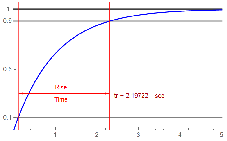
Rise time is defined as the time for a waveform to transition from 10% of the final steady-state amplitude to 90% of that amplitude (fall time is defined the same way … only on the falling edge).

Calculating for a 1st-order response:
![]()
![]()
![]()
Define the low-pass bandwidth by the frequency where the amplitude has decreased by 3dB:
![]()
For ![]() = R C:
= R C:
![]()
![]()
![]()
So the minimum rise time needed to meet bandwidth requirements is found from:
![]()
And a minimum bandwidth of ![]() MHz is required to maintain a rise time of 50 ns.
MHz is required to maintain a rise time of 50 ns.
A handy little equation.
Why is this useful? All practical systems are ultimately limited by a reasonable approximation of a 1st-order low-pass filter – often the construction platform such as the PCB or IC process. As a rule-of-thumb, the system operating frequencies should be about 1 decade below the corner frequency when assuming 20 dB/dec attenuation (a voltage or current factor of 10).
If my system has a corner frequency of 1 GHz, the minimum theoretical and usable rise time would be 350 ps. Allowing a fudge-factor of 10, the minimum rise time would be 3.5 ns. This may have an effect on clocked systems, particularly when non-over-lapping clocks are incorporated in the design.
Kids Say the Darnedest Things
I’ve heard it stated by people that should know better that “rise time” only applies to 1st-order systems. Variations of the magnitude limits exist (although the 10% to 90% limits are standard for analog and digital electronic systems), the concept of rise time most definitely exists for 2nd-order (and higher) systems. The concept is particularly important in high-speed transmission systems.
In this 2nd-order illustration, the steady-state amplitude is 1.0, the rise time is 1.26 sec … and the ±5% settling time is 10.8 sec – but settling time’s a different topic (the CYN region defines ±5% limits)

That’s good for now.
