I’ve not kept up with this technology in 15 years or more – after my time in mineral and oil/gas “prospecting” instrumentation, life took me back to spacecraft.
Much if not most of my career has been involved with space-based instrumentation with the primary challenges being temperature, radiation, mass, volume, and survivability – but by far the most challenging environment I’ve worked with has been geothermal/oil field drill-string instrumentation.
One of my more interesting (fun) experiences was getting to perform some experiments at Chevron’s lab near Tulsa Oklahoma. I wonder if I still have copies of my notes from that experience? It was quite a while ago.
“RF” isn’t necessarily “high” frequency; it’s the region where the dielectric term of the wave equation becomes significant. Some of this “low-frequency” work should be considered RF.
I was first involved in borehole electronics for geothermal applications – corrosive minerals and very high temperatures. At that same time, I also worked on projects for what is now known as “fracking” (inducing micro-fractures in oil-bearing rocks to increase fluid permeability). Almost got a patent for some work in that field … but it wasn’t horseshoes or hand-grenades, “close” doesn’t count.
Also did some borehole work for mineral exploration – it’s expensive to miss the target – but mineral exploration was shallower with bigger pipes and fewer problems – more often the instrumentation went downhole after drilling; most often, the samples were brought up-hole for examination.
A typical well-log appears similar to this. This is an actual plot with ID features stripped off.

Close study shows a number of different types of information. The GRN lines are the actual path of the drill-string – essentially a long pipe: 4000 ft or so down to the region of interest and at least 3500 ft horizontal along the material seam. 10-20 thousand feet of pipe wasn’t unusual – I suspect that hasn’t changed.
The geophysical model is indicated with exploration seam limits. The differences between the geophysical model and real rock is indicated. Nothing like reality to ruin a perfectly good model. (Happens with climate “science” as well – but oil models expect actual real results). The gamma (radiation) levels are also shown (radiation is natural to rocks in spite of what the anti-radiation-at-all-costs crowd thinks).
Study of the plot shows a couple of places where the drill-head left the target area … usually detected by a difference in materials forced to the surface. By the time the material comes up, the bit has travelled far into the wrong region – and drilling the undesired region could ruin the bit. Oop$$
It is expensive in time and money for the bit to leave the desired region; occasionally requires the entire string to be pulled back up the surface and then replanted. Not a quick process.
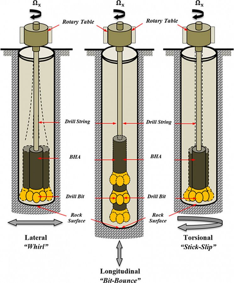
At the end of the drill-string is a bit looking similar to the figure – other configurations are also used but with the same general principle

There are several methods of activating the bit as illustrated. The mud flows down through the center, the waste material is flushed up.

What isn’t shown here is the “mud” flow used for lubrication. The drilling mud is a fluid slurry which is forced down the pipe; it both lubricates the system (under tremendous pressure at those depths) and drives the bit. It is the motion of this mud that is of interest to me for instrumentation purposes.
Positional instrumentation needs to be close to the drill-head. As should be expected, the g-forces are far greater than that of spacecraft launch. Temperatures are high rather than low (although heat accumulation is a concern in spacecraft as well). Space is tight; any electronics needs to fit within the (typical) 2⅞ pipe – and leave room for mud transport. This often requires a donut shaped PCB.
Power is derived from a mud-driven turbine. This electrical power source can’t absorb too much mechanical power from the mud stream; the mud’s primary purpose is to drive the drill bit.
Then we consider communication. How does the data get transmitted to the surface semi real time? One method is to pulse the mud stream. This works functions but is inefficient with very low bandwidth.
One proposed alternative method is shown:
Each section of drill-pipe may or may not be electrically conductive. Assuming steel with occasional conductivity breaks, placing a transmit/receive coil pair every few thousand feet of pipe allows an electromagnetic transfer of data through the steel pipe. The steel should allow transfer of the information with low losses due to the conductivity of the drill mud and surrounding material – adjustments to transmit length made for the presence of salt water would be necessary though. Communication bandwidth would still be relatively low (in terms of free-space transmission) so that skin-effect would not be an overly-significant issue.

Looking back, I’ve worked far too many projects that get to this stage and no further – at least so far as my involvement was concerned. Perhaps something along these lines is used today. It’s a lot more interesting to see an idea work – or at least not work.