A circuit that I always felt useful yet never had the opportunity to actually put into a circuit. Drs. John Kleppe and Larry Huelsman introduced me to these networks. Dr Huelsman was one of the early developers of these networks (and one of my MSEE advisors).
Initial applications were for developing synthetic inductances. First introduced in the 1940s, my recollection is that the use of these networks “peaked” in the mid-70s to early 80s.
This is not a detailed discussion on gyrators; simply a quick representation of two possible implementations.
The synthetic inductor is useful in filter development – note that there are other applications: negative-impedance converters being a significant one.

The admittance matrix of this structure:
![Rendered by QuickLaTeX.com \left[\,Y\,\right] \;=\;\begin{bmatrix}0 & \frac{R4}{\,R1\,R2\,}\\-\frac{1}{\,R3\,} & 0\end{bmatrix}](https://davemcglone.com/wp-content/ql-cache/quicklatex.com-c7538be9b1db1d59bbf250cb61a3ca20_l3.png)
![]()
Assuming equal value resistors and placing a capacitance in the place of ![]() results in an impedance Zi of
results in an impedance Zi of ![]() .
.
While the use of opamps has advantages, a possibly simpler structure using cross-coupled differential pairs can also simulate a floating inductance.
A simplified representation is shown:

![]()
![]()
![]()
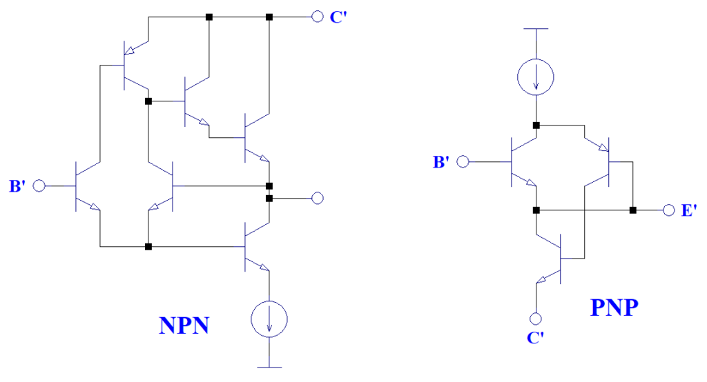
This idealized structure requires high transconductance PNPs and NPNs … a bipolar or biMOS process seems the best choice.
Two transconductance-enhancement networks are suggested

An alternate – floating – topology is shown. This is the first version I learned

Consider the admittance between A & B. For current flowing from A to
![]()
Consider:
Z1 and Z5 are capacitors; Z2, Z3, nd Z4 are resistors
![]()
A component transformation of 1/s is applied such that
- R = r → C = 1/r
- C = c → D = c s
- L = 1 → R = 1
Interesting network. I regret not being able to play with integrated implementations.