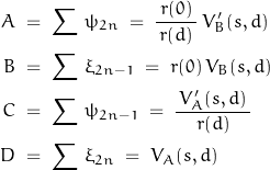
It’s time to readdress the definitions of parameters as they pertain to a general 2-port network which may consist of a distributed network:

Define V1 = V(s,0) and V2 = V(s,d)
![]()
The 2-port transmission parameters are stated as:

And it turns out that y12 = y21
Defining the solutions are a straightforward derivation, the voltage solutions generally result in transcendental functions having no closed forms. Solutions are then obtained from truncated infinite series forms.
A 2nd-order differential equation has two independent solutions; the complete solution may be expressed as:
![]()
where coefficients a and b are defined by the system boundary conditions and VA and VB are the independent solutions.
Normalizing the basic solution at x = 0 is given as:

VA and VB are both functions of s and x. Two properties are observed in the interval x between 0 and d:
where Z(s,x) = Z(s) F(x) and k is a constant independent of x; k is found to be equal to ![]() .
.
![]()
This helps provide a solution for the short-circuit admittance parameters. The basic solution set is expressed:
![]()
![]()
At the input:
![]()
![]()
At the output, the y-parameters are expressed:

These still only represent a general case solutions lacking specific knowledge of the distributed network.
For a uniformly distributed RC network:
![Rendered by QuickLaTeX.com \begin{displaymath}\begin{align}V_A(s,d)\;&=\;\mathit{cosh}[\,d\,\sqrt{\,r\,c\,s\,}\,]\\\\V_B(s,d)\;&=\;\dfrac{\,\mathit{sinh}[\,\sqrt{\,r\,c\,s\,}\,]}{\,\sqrt{\,r\,c\,s\,}\,}\\\\V'_B(s,d)\;&=\;\mathit{cosh}[\,d\,\sqrt{\,r\,c\,s\,}\,]\end{align}\end{displaymath}](https://davemcglone.com/wp-content/ql-cache/quicklatex.com-42ea5d509e6e720f3818251a8047a284_l3.png)
with the zeroes of ![]() and
and ![]() located at
located at
![]()
while the zeroes of ![]() are located at:
are located at:
![]()
The advantage of pre-defining a basic solution set may be seen in a representative expression for the distributed RC network”
![]()
The other admittance parameters have similar expressions … left as an exercise for the reader.
Keeping in mind that VA and VB are transcendental functions, the difficulty of using this solution methodology may be appreciated and explain why this writer has not repeated the experience since grad school … and is not willing to undergo the experience again. Beyond transcribing my notes for posterity on this site.
The internet lives forever.
Hello future!
The open-circuit impedance parameters are found in a similar manner.

With the other parameters found in a similar manner.
The functions describing the solution set generally do not have closed form, but infinite power and product series are more useful in determining pole-zero locations anyway.
The Picard Method is one means of determining a solution set. Assume:
![]()
and set-up:
![]()
where Z is the per unit length series impedance and Y is the per unti length shunt admittance
The approximate solutions are of the form:

where ![]() and
and ![]() are the voltage and current at point x and
are the voltage and current at point x and ![]() and
and ![]() are the input voltage and current as defined below:
are the input voltage and current as defined below:

The parameters are defined:

![Rendered by QuickLaTeX.com \begin{displaymath}\left[ \begin{array}{c}V_x \\ -I_x \end{array} \right]\;=\;\left[ \begin{array}{cc}\sum \, \xi_{2n} & \sum \, \xi_{2n-1} \\ \sum \, \psi_{2n-1} & \sum \, \psi_{2n}\end{array} \right]\;\left[ \begin{array}{c}V_1 \\ -I_1 \end{array} \right]\end{displaymath}](https://davemcglone.com/wp-content/ql-cache/quicklatex.com-8fe25b863d0eff844b27f4885f67cf3c_l3.png)
The short-circuit admittance parameters are:
![Rendered by QuickLaTeX.com \begin{displaymath}Y\;=\;\left[\begin{array}{cc}\dfrac{\sum \, \xi_{2n}\,d}{\,\sum \, \xi_{2n-1}\,d\,} & -\dfrac{1}{\,\sum \, \xi_{2n-1}\,d\,}\\\\-\dfrac{1}{\,\sum \, \xi_{2n-1}\,d\,} & \dfrac{\sum \, \psi_{2n}\,d}{\,\sum \, \xi_{2n-1}\,d\,}\end{array} \right]\end{displaymath}](https://davemcglone.com/wp-content/ql-cache/quicklatex.com-058b9931a70113af0ac44efa53217930_l3.png)
where

This methodology is suitable for determining solutions for non-uniform lines.
That’s good for now. Next: An Example
