There is a lot of math in this article. I go through the excruciating detail I once went through as a student … and didn’t bother with again. Professionally, I cared about the results of these analyses, not the derivations. However, an exercise necessary for my PhD work – propagation through the earth may be considered a (non-linear) distributed network.
In hindsight? A worthy exercise for the student – it forces the foundation of this topic into reluctant brain cells. A few times I recall, I used this as a “model” so to speak but going through it again this time? It’s good to document it one last time so I don’t need to bother again.
Most analyses assume lumped parameters: component values are constant throughout the circuit. One way to characterize this is to note that in a lumped-parameter network, the wavelengths are large compared to the physical circuit dimensions. For example, in free-space, a 30MHz signal has a wavelength of about 10m. Most circuits are smaller than that.
These systems may be represented with ordinary differential equations. However, not all systems can be considered as lumped networks; I’ll attempt to demonstrate procedures where the lumped parameter assumptions do not hold. Some of these situations are transmission lines, integrated circuit components, thermal signal conduction, etc. This discussion is not intended as a comprehensive analysis, but should provide a basic understanding for the more common distributed RC and LC networks.
Consider a transmission line which has a dependency on dimension x. A general model of this is shown:

where each element has a value dependent on an incremental length value of Δx. The approximation becomes more accurate as Δx tends to 0.
The distributed parameters are resistance R (Ω/m), inductance L (H/m), capacitance C (F/m), and conductance G (S/m).
The circuit equations for this network are:
![]()
![]()
Dividing by Δx and taking the limit as Δx tends to 0 gives the partial differential equations:
![]()
![]()
Assuming v(t,x) and i(t,x) have Laplace Transforms with respect to time and differentiating with respect to x gives:
![]()
Conditions at specific values of x are boundary conditions; those at specific values of t – often 0 – are known as initial conditions. If the initial conditions are zero, we may state the partial derivative circuit equations as:
![]()
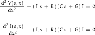
Differentiating with respect to x – assuming R, G, L, and C are not functions of x – and that a derivative in s does not occur gives:
![]()
For a uniform transmission line:

The solutions to these equations are given as:
![Rendered by QuickLaTeX.com \begin{displaymath}\begin{align}V(s, x)\,&=\,A_1\,\mathit{cosh} \left[\Gamma\right]\,x\,+\,A_2\,\mathit{sinh} \left[\Gamma\right]\,x\\\\I(s, x)\,&=\,B_1\,\mathit{cosh} \left[\Gamma\right]\,x\,+\,B_2\,\mathit{sinh} \left[\Gamma\right]\,x\end{align}\end{displaymath}](https://davemcglone.com/wp-content/ql-cache/quicklatex.com-93ad7909dcb9e5c65898219d8afaf833_l3.png)
where ![]()
The coefficients are not dependent on x and are determined from boundary conditions. Assuming a finite length d, the boundary conditions are stated as:

The ratio V(s,0) / I(s,0) is not a constant for finite and non-uniform transmission lines.
The coefficient values A1 = V(s,0) and B1 = I(s,0)
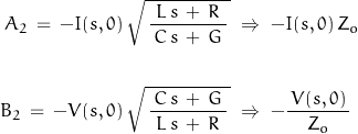
Differentiating with respect to x and setting x = 0

where Zo is the characteristic impedance of the transmission line.
The network may now be represented by the following model:

which may described by:
![Rendered by QuickLaTeX.com \begin{displaymath}\left[ \begin{array}{c}V_1 \\ I_1 \end{array} \right]\;=\;\left[ \begin{array}{cc}A & B \\ C & D\end{array} \right]\;\left[ \begin{array}{c}\,V_2 \\ -I_2 \end{array} \right]\end{displaymath}](https://davemcglone.com/wp-content/ql-cache/quicklatex.com-72864b34fd633c5b55d6524d76e68f00_l3.png)
That’s good for now. Next: Cascaded Networks
