The concentration of CO2 in the atmosphere doesn’t vary greatly in terms of signal magnitude. Of more significance will be the common-mode signal related to the environmental factors. The largest variation will be reflectivity.
The reflected source would not be a directed beam, optical power would be lost due to semi-Lambertion diffusion and the inverse square rule. However, within the constraints of the system geometry and assuming the receiver effective field-of-view (FOV) is 100%, the optical power that is received would have been again subject to the Beer-Lambert law after reflection.

Reflectance is also dependent on wavelength. Some typical “earth” surface materials have spectral responses as shown below – with reflectance in percent over wavelength in μm. The pink rectangle is the spectral range of my interest for this discussion. Note the fairly low values.

Lambertian Reflection
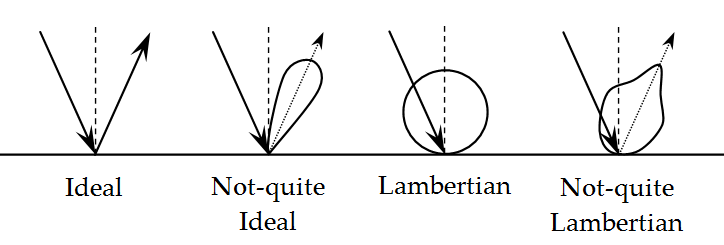
Due to the principles of superposition, the surface of reflection may be considered a source. However, unlike the transmitted laser beam, the reflecting surface a diffuser and the reflected light is often considered a Lambertian source (depending on the reflecting material and other factors).
A true Lambertian surface is isotropic and diffuse – a “matte” or even “flat” appearance. A primary characteristic is that the apparent brightness of the reflection is the same regardless of viewing angle – radiance being power per unit solid angle per source area. Wikipedia suggests coal and fresh snow as examples of Lambertian surfaces with low and high reflectivity. Other surfaces will have varying degrees of specularity – localized regions of high reflectance. The ocean surface is considered Lambertian but ripples on the surface would add specularity (and could cause optical saturation of the detector). However, water is a good absorber of IR and is not likely to reflect a significant signal in any case.
Some idealized reflection patterns are illustrated:

In reality, the reflection pattern is likely to be a more complex hybrid between the “not-quite” ideal and “not-quite” Lambertian patterns as shown here.
The intensity of the reflection is highest for illumination and reflection normal to the surface.
The detector will see this reflecting surface as a two-dimensional area. At a long distance between reflector and detector, the surface is initially treated as normal to the detector and symmetrical about the normal axis.
The aircraft platform moves at 200 m/s. The optical travel time is 67 us at 10 km altitude. The aircraft moves 13 mm in that period of time; for such time increments, the measurement platform may be considered static and the reflection angle is normal to the surface.
This drawing is illustrative but grossly out of scale; the angle θ is roughly 0.15 mrad (8.6e-3 degrees aka 30.94 sec). Very small. Almost a columnar cylinder. (The ideal reflecting surface is 1.5 m radius; the initial aperture of the telescope is 0.2 m)

For a Lambertian reflecting surface of circular radius r = 1.5 m, distance to detector Z = 10 km, and reflected intensity Φ = 1 W:
![]()
But I believe the Lambertian assumption to be overly-pessimistic.
Gross reflectivities (albedo) of some effective earth materials:
(http://www.physicalgeography.net/fundamentals/7f.html)
Snow, fresh: 80-95%
Sand, dry: 35-45%
Forest, deciduous: 5-10%
Forest, coniferous: 10-20%
Grasses: 15-25%
For all intents and purposes regarding the detector, what this implies is a signal range having intensity of close to a perfect reflector to that of a perfect absorber. The detector will define the maximum dynamic range and minimum detectable signal; the source intensity will define the maximum detectable signal. Everything in between will tend to attenuate those limits.
For my purposes, the use of an ideal reflection may actually be appropriate as I’m defining instrumentation limit parameters … but that may be overly conservative (except when defining worst-case non-destruction limits). For “normal” signals, I’ll use 85% of the incident intensity as the maximum reflected intensity … until further analysis suggests otherwise.
That’s good for now.
![]()