Integer fractions.
Alan Turing defined numbers in 1936 “sequences of digits interpreted as decimal fractions” between 0 and 1. I’ll add that the numerator of these decimal fractions are represented as integer “counts” in binary format. The denominator is fixed at a value of 2 .
.
For example, if I use a reference value of 1 and want to know the fractional equivalent of 0.7 to the nearest 8th, I select a divide-by-8 (N = 3) ADC and find that the closest integer value of the numerator of 0.7 is 6 (as in 6/8) which is represented in binary form as 0110. The binary output can then be re-converted into a decimal number – which in this example is 0.750.
The ADC introduces error: this output is 7.1% higher than the “real” value. I can decrease that error by changing the denominator (which requires the selection of a different ADC).
So I increase the denominator by increasing N by 1 (to 16ths – N = 4) and I now find the closest value of the numerator is 11 – which is represented in binary as 01011. The binary output can then be re-converted into a decimal number – which in this example is 0.6875 and is only 1.8% lower than the true value. The value of N is referred to as the “number of bits” and defines the ADC resolution.
If a 10-bit converter were used, a bit count of either 716 (0.69922) or 717 (0.70020) would result. If a 12-bit converter were used, a bit count of either 2867 (0.699951) or 2868 (0.700195) would result. If a 16-bit converter were used, a bit count of either 45875 (0.699997) or 45876 (0.700012) would result.
Values for N of 3 or 4 are not commercially feasible (although TI sells a 4.5 bit converter); the most common values being 8, 10, 12, 16 with 14, 20, 24 only slightly less common. 32-bit (and possibly higher) devices are also available.
What I’ve been calling an ADC is best divided into two functions: sample (or “track”)-and-hold and quantization. Make the “instantaneous” measure, then hold that value while the quantizer converts the magnitude of the measure into the digital word that most closely approximates that value.
The process of converting an analog signal to a digital one may now be represented as:
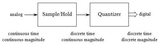
This is simply a representation of the process, the actual process may differ slightly from this (there are different methodologies of implementing analog-to-digital conversion … but I’ll stick with discussing this basic one).
This representation emphasizes the fact that each of these contribute different forms of signal distortion to some degree. While these functions are often combined as “part of the package”, it may be that there’s an application for isolating the two: The Analog Devices AD585 is one example of a discrete S/H; the AD574 is a discrete 12-bit ADC. Both have been around for decades; both are still in production.
Along with Analog Devices (which recently purchased Linear Technology), I’d also look at TI (which in the past has purchased Burr-Brown and National Semiconductor among others).
Keeping track of the players gets difficult when they start playing musical chairs with each other. Precision Monolithics (OP-07 – 1975) was pretty good in its day. Not sure who swallowed them up (oops: Analog Devices – 1990) But I’ve found the best of the heritage parts are still available … and if they weren’t good parts, they’d have disappeared long ago …
I discussed “ideal sampling” in Part 7, but that discussion was based on the theory of sampling with “impulse” functions – but the sampling process is not instantaneous – nor is the quantization process. True impulse sampling is not possible in physical circuits; circuit resistance and capacitance – distinct or parasitic – slow the process. The impulse has devolved into a pulse having finite time width.
The sample/hold (S/H) network – or its cousin, a “track and hold” (T/H) – samples the input analog signal and holds it – usually as charge on a capacitor (V = Q/C). There are several issues of interest within this topic – many having to do with the response to a sudden change of state between the SAMPLE-HOLD-SAMPLE sequence; many having to do with sequence timing. These are issues because the quantizer typically requires a constant value while doing its thing in converting the analog information to a representative digital word.
The quantizer itself has items of concern. While it’s not likely the typical designer has the ability to tweak the details of operation, it is useful to have a glimpse of those details in order to choose between the gadzillion or so varieties of ADCs available.
That’s good for now.
![]()