Integration
I want to examine the effects on noise of these two integration networks. Effectively, they both perform the same function: control the accumulation of charge on a capacitor over time.
The first network has a voltage input. When the switch closes (a “step” function), the voltage Vin is applied to the capacitor. The amount of accumulated charge at steady-state is defined by Q = C × V. In the absence of other conduction paths (with an infinite load impedance), that charge will remain on the capacitor while the switch is open.
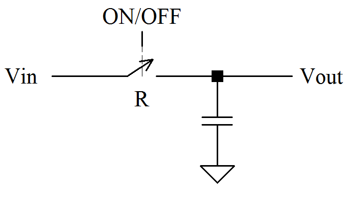
In voltage mode, it has been shown that the voltage noise on an RC network is ![]() . At ambient temperature with a 1 pF cap, that rms noise is 64
. At ambient temperature with a 1 pF cap, that rms noise is 64 ![]() V … or near on 400
V … or near on 400 ![]() V peak-peak. That’s a fair amount of noise for a low-level signal. Note the noise is independent of voltage – and assumes a noise-free voltage source.
V peak-peak. That’s a fair amount of noise for a low-level signal. Note the noise is independent of voltage – and assumes a noise-free voltage source.
An alternative may be this integrator network – a form of transimpedance function – which converts a current input to voltage output:
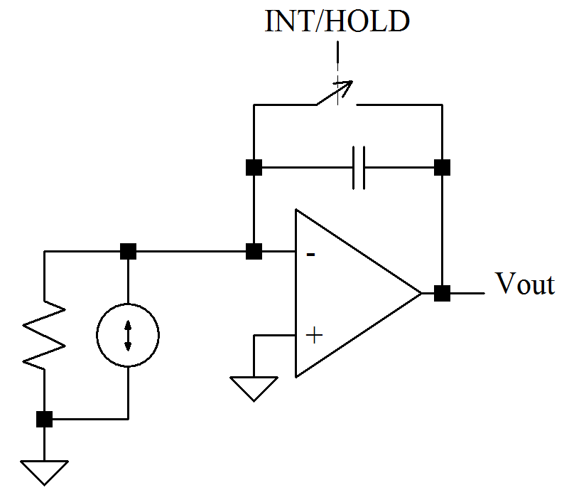
The resistor represents the shunt impedance of a current source – a photodiode perhaps? – with current noise source indicated. The opamp connection forces the inverting input node to be 0V. No current flows into the opamp – it all flows to the capacitor. This accumulating charge builds a voltage which is referenced to the inverting input node – 0V in this example … forcing Vout to have a magnitude of -(Q/C).
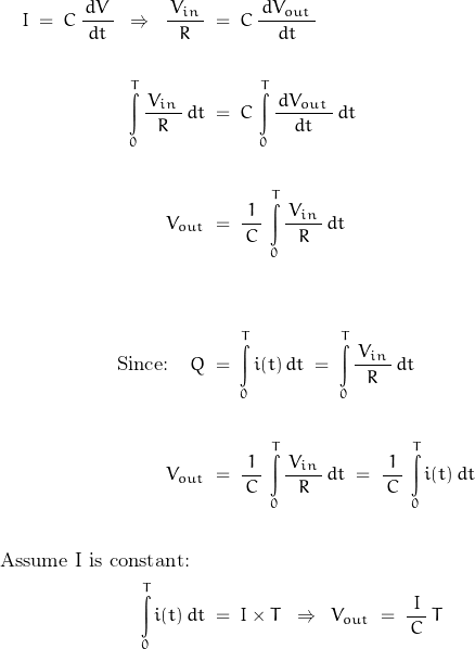
The expression relating current, capacitance, and voltage is commonly given as:
![]()
In most cases, this expression is adequate but the full expression is:
![]()
This suggests sensing elements and measurement methods based on a varying capacitance.
A photodiode with dark current of 10 nA and reverse-biased at 0.7V has a shunt resistance of 70 M![]() . The RMS current noise of the resistor is:
. The RMS current noise of the resistor is:
![]()
The resistor is at GND potential at both terminals; the noise current flows into the capacitor such that the current noise of the resistor is transferred to the output voltage as:
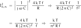
Traditionally, noise is given in units of volts or amps per root Hz. To maintain this convention:

![]()
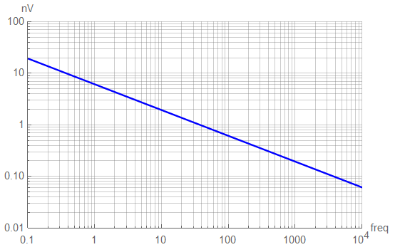
Not that it makes any difference to the result …
Not as bad as calculating kT/C noise would suggest … but this last was current-mode, not voltage-mode.
Integration of S(f)
With the growing prevalence of switched-mode processing, there’s plenty of opportunity for integrating the results of integration …
Why should this matter if the world is digital? Because this integration often occurs before quantization and adds to the degree of uncertainty.
The magnitudes of many noise signals are given in units of “per root Hz” and are often described in the following form:

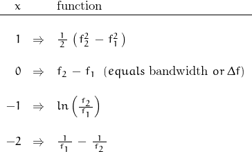
So let’s quantify the integration of various orders of f. The base function will be of the form:

for each ![]() of
of ![]() :
:
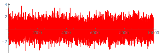
Thermal noise will appear similar to:
Brownian noise (aka “randomwalk”, “brown”, “red”) is produced by the integration of white noise. The power spectrum of Brownian noise is proportional to 1/f² and will appear similar to:
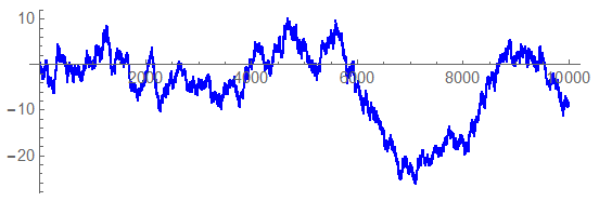
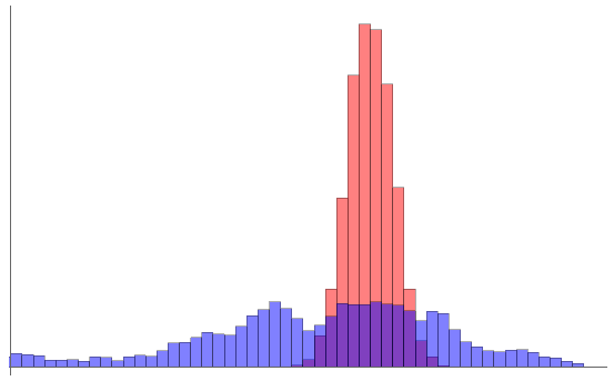
The distribution of samples is illustrated with a histogram. RED is white noise; BLU is Brownian noise:
The “quality” of the Gaussian distribution assumption can be determined from the statistical characteristics:
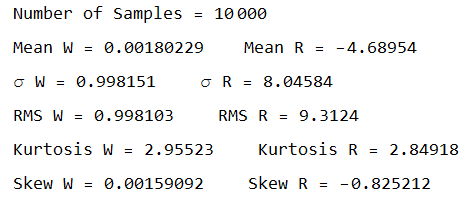
A “pure” Gaussian distribution with mean 0 and variance 1 has kurtosis of 3 and skewness of 0. This example set of 10,000 sample points of white noise comes close to the ideal.
The RMS voltage value of Brownian noise is determined by:

Now consider the effect of averaging the Brownian noise; start with approximating the frequency limits.
If the measurement time per sample is ![]() , then the effective measurement time for N samples is N
, then the effective measurement time for N samples is N![]() . The high frequency limit tends towards (relative) infinity, but as each sample is added, the effective measurement time increases – fL decreases such that this approximation is valid:
. The high frequency limit tends towards (relative) infinity, but as each sample is added, the effective measurement time increases – fL decreases such that this approximation is valid:
![]()
The Brownian RMS voltage may now be approximated by:

The low frequency noise increases as f![]() (flicker) and f
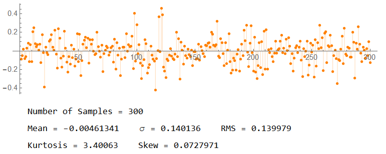
(flicker) and f![]() (Brownian), therefore the low-frequency noise increases as the square root of the effective measurement time. (One way to express this is that flicker and Brownian noise dominates white noise at lower frequencies. While averaging will decrease the effects of white noise, it will increase the effects of flicker noise).
(Brownian), therefore the low-frequency noise increases as the square root of the effective measurement time. (One way to express this is that flicker and Brownian noise dominates white noise at lower frequencies. While averaging will decrease the effects of white noise, it will increase the effects of flicker noise).

That’s good for now.

Part5
Part 7