Amplifiers
The information from the majority of transducers is not suitable for direct quantization. The typical – sometimes only – method of pre-quantization signal processing is amplification and filtering (frequency-dependent convolution). There are many advantages to including higher degrees of mathematical operations at this stage beyond simple gain, but that represents a different topic …
When amplifiers are used, it is usually a voltage-mode operational amplifier operating with negative feedback. A good voltage-mode opamp has high input impedance (→ ∞), high open-loop gain (→ ∞), high bandwidth (→ ∞), and low output impedance (→ 0). For practical purposes, a real opamp may come close to effectively realizing these criteria at low frequencies (in engineering terms rather than mathematical) with the validity of these approximations deteriorating as frequencies increase.
The amplifier itself functions as a low-pass filter (albeit somewhat uncontrolled), so it makes sense to combine gain/filter functions – after all, a filter is nothing more than a frequency-dependent gain/phase modifier … as is an amplifier1.
The parts of an amplifier’s gain/frequency curve are highlighted in the following figure:
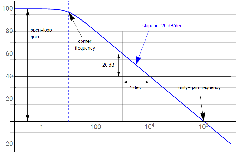
The “gain-bandwith product” (GBP) is based on the asymptotic -20 dB/dec slope inherent to 1st-order attenuation. In the region where the slope is considered constant, the GBP indicates the trade-off between gain and frequency. This value is defined by the unity-gain frequency; 1 MHz in this figure.
Applying the GBP principle, the amplifier will provide a gain of 100 (40 dB) up to a frequency of 10 kHz (100 ![]() 10,000 = 1,000,000). The amplifier can provide a gain of 1000 to a frequency of 1 kHz … and so forth. The asymptotic limit occurs at the open-loop gain corner frequency: a gain of 100,000 to a frequency of 10. The open-loop gain is the maximum gain available.
10,000 = 1,000,000). The amplifier can provide a gain of 1000 to a frequency of 1 kHz … and so forth. The asymptotic limit occurs at the open-loop gain corner frequency: a gain of 100,000 to a frequency of 10. The open-loop gain is the maximum gain available.
Gain Error
The gain of an opamp is not actually infinite although DC open-loop gains of 10,000,000 (140 dB) are available. This finite gain can lead to gain error. When the amplifier is used as a buffer, the closed-loop gain is often set to unity. Following the GBW principle, the corner frequency would be the unity-gain frequency. This configuration is often used as an impedance transformer with high input impedance and low output impedance (suitable for matching low impedance sources such as voltages to high impedance loads – such as another opamp). It is usually implemented by setting the feedback factor β to 1, shown schematically as:
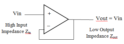
In reality, the amplifier has finite open-loop gain which modifies the closed-loop gain expression:
![]()
with the feedback factor
With infinite open-loop gain, the closed-loop gain is determined by:
![]()
However, if the open-loop gain is 1000 (60 dB), the closed-loop gain is:
![]()
A gain error of about -0.1%.
This may seem insignificant but at this value could be a limiting factor on measurement accuracy. However, most precision amplifiers have open-loop gains substantially higher than 60 dB. An amplifier with a more typical open-loop gain of 100k (100 dB) has a gain of 0.999990 – close enough to 1 for most situations.
At the higher end of available open-loop gain – say 140 dB, the closed-loop gain is:
![]()
This gain error is insignificant … and barely measurable – and not sustainable at frequencies much above 10 Hz or so.
I can work this backwards … consider a 1 V signal requiring resolution to 1 mV or better through a unity-gain buffer (![]() ).
).

For which the illustrative amplifier with
The closed-loop gain error at gain of 1 is plotted as a function of the open-loop gain. The bounds for 1 LSB error for both a 12-bit and 16-bit ADC are also shown. The top line represents the ideal gain in units of dB (gain = 2 ≡ 6.0206 dB).
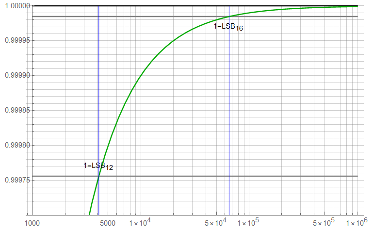
This plot shows the open-loop gain required to reduce gain error to less than 1LSB for 12 and 16-bit converters. An open-loop gain ![]() of about 72 dB is required for 12 bits; about 96 dB for 16 bits. These are not difficult requirements at very low frequencies; for example, the Linear Technology LT1028 has a typical open-loop gain of about 150 dB to a corner frequency of about 2 Hz. With roll-off of 20 dB/dec, I can maintain a gain of 96 dB to about 2 kHz (again, other amplifier characteristics need to be considered as well).
of about 72 dB is required for 12 bits; about 96 dB for 16 bits. These are not difficult requirements at very low frequencies; for example, the Linear Technology LT1028 has a typical open-loop gain of about 150 dB to a corner frequency of about 2 Hz. With roll-off of 20 dB/dec, I can maintain a gain of 96 dB to about 2 kHz (again, other amplifier characteristics need to be considered as well).
Taking measurements to 16-bit precision requires special care, so the use of “specialty” – i.e., expensive, hard to find, long lead time2 – parts should not be unexpected. Simply placing a 16-bit converter in the signal path will provide 16-bit resolution but does not assure 16-bit accuracy or precision. GIGO. The information at the ADC input also needs to meet 16-bit requirements as do the effects of environment variations.
Bandwidth Error
An efficient pre-quantization design usually incorporates both gain and filtering although this is only a generalization. A physical opamp itself is an inherent 1st-order low-pass filter, but a proper design is such that the amplifier is “invisible” to circuit operation; i.e., the amplifier should appear ideal with regards to the overall network. Gain should be controlled by external components, system bandwidth should be limited such that the amplifier bandwidth does not interfere with signal integrity – think phase. Amplifier limitations should have minimal effect on circuit performance.
It is common (and usually desirable) to combine gain/filter functions – after all, a filter is nothing more than a frequency-dependent gain/phase modifier … as is an amplifier.
The typical op-amp has a single dominant pole at frequencies lower than the unity-gain frequency (with additional poles located at higher frequencies – in regions of amplifier attenuation). Therefore, the frequency dependent open-loop gain may be expressed as:
![]()
where
As an illustration, assume an opamp with open-loop gain of 1000 (60 dB) and a -3dB frequency of 50kHz. The single-pole roll-off implies a decrease in amplitude of -20dB/dec; a simple calculation indicates that this amplifier has a unity-gain frequency of 1000 ![]() 50 kHz = 50 MHz. Graphically, the asymptotic approximation for this amplifier appears as:
50 kHz = 50 MHz. Graphically, the asymptotic approximation for this amplifier appears as:
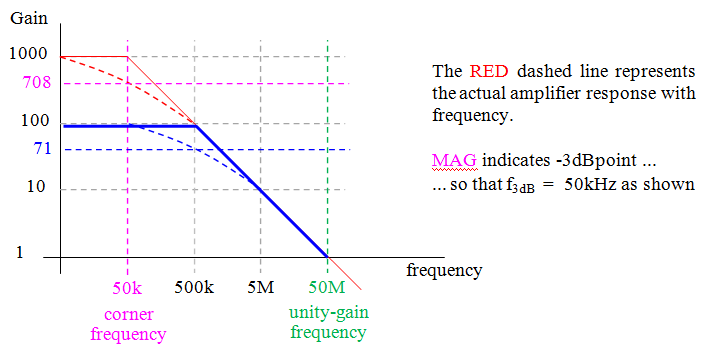
Note that the asymptotic approximation causes magnitude errors within ![]() 1 decade about the corner frequency with almost 30% error at the corner. The magnitude error is 0.5% or greater for frequencies within
1 decade about the corner frequency with almost 30% error at the corner. The magnitude error is 0.5% or greater for frequencies within ![]() 1 decade of f
1 decade of f![]() .
.
This amplifier has an open-loop gain (RED) of 1000 (60 dB), a corner frequency of 50 kHz, and a unity-gain bandwidth of 50MHz. But consider: if a closed-loop gain (BLU) of say 100 (40 dB) is desired, the “ideal” signal frequency limit is 500 kHz. Note that the amplitude response at 500k begins to be affected by the asymptotic approximation: there may be significant differences in the signal amplitude due to differences between the actual response and approximations made in the analysis. Problems of this sort may require multi-stage amplification.
Consider the effects of this decrease in amplitude. The “-3dB” point in this illustration is at 50 kHz. By Nyquist criteria, one might expect that a minimum sample rate of 100 kHz would be required.
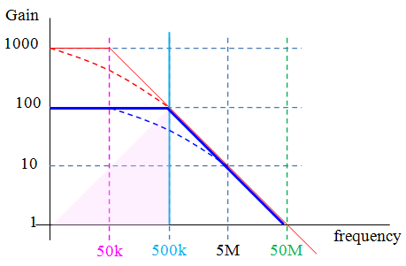
However, consider a sample rate at 500kHz. The signal components above 500 kHz remain strong enough (50% at 1 octave; 10% at 1 decade) to introduce significant aliasing effects into the quantized data. The Nyquist limit is a mathematical nicety – in practice, the sample rate should be greater than Nyquist.
The aliased signal folds into the region in PNK. A sample rate at the Nyquist frequency is generally insufficient to prevent errors due to aliasing even in a noise-free system (assuming signal frequency components above Nyquist – if it were known there were only insignificant frequency components above Nyquist, filtering would not be required).
As mentioned previously, amplifiers are typically part of a feedback system. The closed-loop expression previously given is independent of frequency but frequency dependency is among the first non-ideal characteristics to be added to the ideal model.
![]()
where
Time Response
An opamp is more accurately modelled as a two-pole system but the second pole (usually) occurs below the unity-gain frequency and may be ignored for a conceptual discussion such as this. If phase response were being considered, this second pole (and possible zeroes) would become more significant. For now, the amplifier may be modelled as a 1st-order, low-pass filter with a single pole at high gain and low frequency.
As such, it has a 1st-order step response which may be expressed:
![]()
The resolution of this response is:
![]()
If the settling time is restricted to no more than 1/2 the sample period ![]() (perhaps not the best practice), then:
(perhaps not the best practice), then:
![]()
which forces a minimum necessary amplifier unity-gain frequency of:
![]()
If the sample rate of this system is 10 MHz, the amplifier requires a unity-gain bandwidth higher than 22 MHz:
![]()
These values represent analytical minimums. In practice, these values should be higher than minimum values (to account for effects not present in this simplified example). This same derivation is applicable to settling time considerations: sufficient time is required for the measured phenomena to settle from the effects of sampling (usually a switch changing state).
One should keep in mind there are other error sources associated with amplifiers – some of which may be significant, others not so much.
That’s good for now.

Part 4
Part 6
1A filter may be thought of as a frequency-defined attenuation element; an amplifier as a frequency-dependent gain element. An active filter can produce gain; the amplifier/filter functions may be mathematically identical.
2Spacecraft-qualified