Direct Current: DC vs. fmin
So what is “DC”? Direct current. Assumes a uniform electron flux. Analogous to a steady flow of water in a pipe. No frequency content … which mathematically implies that the flux began at “minus infinity” and will flow to “plus infinity”. The earth itself is considered to have a starting point so there goes the concept of “minus infinity”. And I’m taking the measurement of a causal system >now< so why bother with “plus infinity”?
So in the strict sense “DC” doesn’t exist. The age of the universe does not extend backward to – … neither do electrical power plants – but “last week” comes close enough for most practical applications. Sometimes “I just turned it on” is sufficient.
Closer to the practicality of defining DC vs. “low” frequency is the effect of turning on equipment … and the effect of both electrical and thermal settling time on precision measurements.
Someone comes into the lab, turns on the equipment, makes a measurement, turns off the equipment, then leaves to process the information. If the turn-on to turn-off duration is 1 hour, the lowest frequency of the system is 1/3600 Hz … 0.2 mHz. This seems sufficient for “approximately DC”.
(One of the HP, oops Agilent, oops Keysight signal analyzers – the 35670A – measures to 122 Hz … a period of 8196 sec – about 2 1/4 hours. For this instrument, a period of 2.25 hours is NOT DC … though most of would consider it so).
Consider a piece of test equipment which is turned on at 9AM on Day 1. It is presumed that the instrument has achieved the proper measurement stability before information is collected at 9AM of Day 2. (A 24-hour stabilization period at constant temperature, say ±1°C, is not unusual for precision test equipment; it is often better to leave high-end lab test equipment ON in a uniform environment at all times.)
The lowest frequency of this system is found to be:
For comparison, consider a system with normalized noise of 1V and a 1 kHz bandwidth with various calculated frequencies.
If:
Does the difference in calculation between the ideal “0” and 0.1 Hz make a difference? Doubtful, especially considering the effects of additional noise sources.
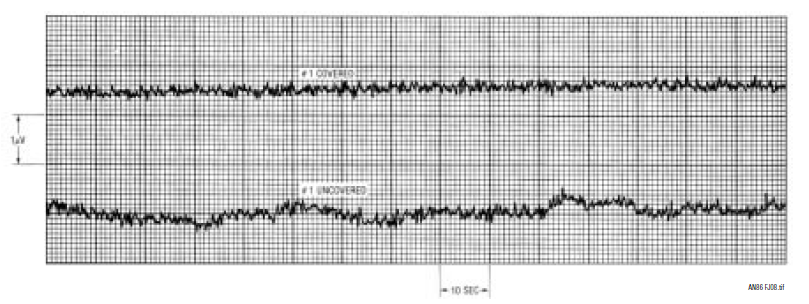
As an example of often not-considered noise sources, the late Jim Williams of the late Linear Technology performed an experiment in which he compared the noise of a circuit in open air and then covered it with a styrofoam cup (not all test equipment needs to be expensive). The results were presented in Linear Technology Application Note 86f and are shown here:

The vertical units are 1 V/div; the time units are 10 sec/div. The lower trace shows the open-air noise of about 900 nVpp; the upper trace shows circuit noise of about 400 nVpp when covered by the cup. Not all noise issues are directly circuit related; the circuit environment may play a large role.
(A set of the Linear Technology app notes written by Jim Williams should be in every analog designers library.)
For reasonable estimates, the turn-on process can be considered limited by a 1st-order system: although higher-order components exist, the act of turning power on is essentially an early-time step function (ramp time << period) applied to a 1st-order system.
Amplitude stability effects are limited by late-time 1st-order thermal diffusion effects. Turning power off may be considered an early time inverse unit-step to a 1st-order system and are typically not a consideration – though it sometimes behooves one to consider capacitor charge. Late time thermal effects during turn-off may suggest that one not touch a hot part immediately after turn-off.

Determining the effective time constants may prove to be difficult – but likely not necessary. Mathematically, it takes about 14 time constants for an ideal 1st-order system to settle to 1ppm. Unfortunately, the use of a 1st-order system for analysis is only a mathematical approximation; unless measuring turn-on characteristics directly, it’s best to leave the circuit in a powered-on state for a substantial time to allow thermal stabilization – the manufacturer will usually provide “guidelines” in the spec sheet. 1 hour is common, I’ve also seen a wait period of 4 hours given. A 24-hour warm-up is not uncommon in high-precision instruments.
For example, an excerpt from the Agilent 3458A User’s Guide (8½-digit Digital Multimeter):

Operating temperature is Tcal ±1°C: Assume that the ambient temperature for the measurement is within ±1°C of the temperature of calibration (Tcal). The 24 hour accuracy specification for a 10 VDC measurement on the 10 V range is 0.5ppm ±0.05ppm. That accuracy specification means: 0.5ppm of Reading + 0.05ppm of Range. For relative accuracy, the error associated with the measurement is: (0.5/1,000,000 x 10 V) + (0.05/1,000,000 x 10 V) = ±5.5 μV or 0.55ppm of 10 V.
The optimum technical specifications of the 3458A are based on auto-calibration (ACAL) of the instrument within the previous 24 hours and following ambient temperature changes of less than ±1°C. The 3458A’s ACAL capability corrects for measurement errors resulting from the drift of critical components from time and temperature.
Thermal time constants in the physical materials and environment may be significantly longer than the electrical ones related to the electronic components of the circuitry and temperature shifts are often more important than absolute temperature. Many high-end lab instruments suggest at least a 24-hour stabilization period; a proper lab environment for making precise small-signal measurements would also be temperature and humidity controlled … a stable environment being more important than the absolute values.
So what do I call “DC” and what do I call “low frequency”?
As always … it depends.
That’s good for now.

Part 2
Part 4