A continuous-time sine wave (BLU) is to be digitized. The waveform is sampled at even intervals (CYN) and the corresponding values are “held” (RED) long enough to be quantized.
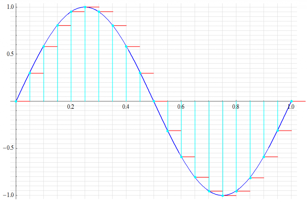
A digital word representing the value of each RED level to the resolution defined by the value of 1 LSB is generated. The intermediary values are not part of the output information. It is the goal of post-quantization reconstruction to emulate this missing information.
OK, now I have my (still “analog”) sample. It exists as charge on a capacitor with a voltage proportional to the number of electrons held. Now I need to approximate that value to the nearest fraction represented by a digital word. But this is where it comes together: What’s the best approximation that may be achieved and how many bits will I need to accomplish this?
Although there many means of coding numbers for downstream computational arithmetic, the basic result is constrained by the length of “word” defined by the ADC – the numbers of bits.
A typical “precision” ADC1 is capable of resolving 1 bit of a 65536 bit count – the equivalent of 0.001526%. This is significantly greater than the resolution most transducers are capable of providing but leaves “headroom” for uncertainty (and inevitable noise) in the converion. A 12-bit converter is likely sufficient (1 part of 4096 – 0.024%) if storage and transmission bandwidth are issues.
The ideal 1 LSB error for common N-bit converters is shown.
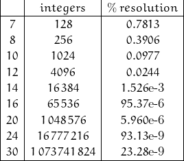
Usually, the converters above 16-bit are some form of mixed-signal topology. I know of a commercial 30-bit converter; I’ve worked with 24-bit versions. I’ve recently become aware of a 32-bit version; I’m sure higher bit count versions are in the works.
Consider the 16-bit conversion. It has a possible measurement resolution of 0.0015%. For FSR = 1V, 1 LSB is equivalent to 15.3 ![]() V. This implies that for an amplitude to be measured to ½ LSB, the amplitude needs to settle to within 7.63
V. This implies that for an amplitude to be measured to ½ LSB, the amplitude needs to settle to within 7.63 ![]() V of its final value.
V of its final value.
The ideal 1st-order system indicated above would require just shy of 12 time constants for the amplitude to settle to this accuracy.
Quantization
The full scale range (FSR) of an ADC quantizes that range of signal – almost invariably a voltage – into a set of discrete representations defined by the bit resolution of the converter. The count of possible quantization levels is expressed as:
![]()
For a 16-bit converter:
![]()
Each count is equivalent to 1 LSB where:
![]()
Any one sample of the signal can have a maximum error of ±½ LSB. The digital representation includes not only the sampled value of the continuous input (including any uncertainties), but also a quantization error (QE) due to the quantization process itself. Most of the time, this quantization error has the characteristics of random noise. This noise has a uniform distribution between ±½ LSB, a mean value of zero, and a standard deviation of 1/ sqrt(12) LSB … or about 0.289 LSB.
Using a 3-bit converter (count = 8) for illustration, the input/output relationship is mapped as:
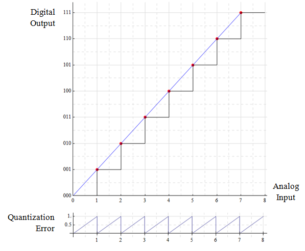
The quantization levels correspond to digital codes 000 → 111 (0 → 7) so that the maximum output of the ADC is 2N – 1. Each code step is incremented by 1 LSB where:
![]()
An inherent error is the result of quantization where quantization error Qe is the difference between the actual input and the resulting code output. This is shown in the lower plot where the maximum error is a full LSB. By shifting the transition point, the error is limited to ±½ LSB.
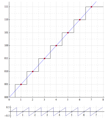
The first transition now occurs at ½ LSB (1/16) and extends to (n – ½ LSB)
The following shows the transition points. There is “dead” area (GRY) below ½LSB and above ½MSB. The analog input range for a constant digital word (ORG) is shown in PUR.
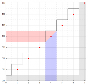
All analog input values between 3.5 and 4.5 are represented by the same digital word: 100. Any information contained within the difference of 3.5![]() and 4.5
and 4.5![]() is lost and can not be accurately recovered from the digital word (and if this is an issue, the converter resolution should be greater).
is lost and can not be accurately recovered from the digital word (and if this is an issue, the converter resolution should be greater).
Quantization Noise
It is not the intent of this discussion to address all the errors associated with ADCs, but quantization noise is inherent to the conversion process and dependent on the degree of quantization (number of bits). For my purposes here, the ADC itself is ideal.
The quantization process adds noise to the system. Perhaps one of the best examples of what is meant by quantization noise is illustrated with a clocked comparator … which is the equivalent of a 1-bit ADC.
Consider an ideal comparator with VDD of 1 V and ½ VDD applied to the inverting input. Assume the signal input on the non-inverting input is ramped up from 0 to 1V. The initial comparator output is 0V until the input signal reaches 500 mV at which time the comparator switches state to an output of 1V. The comparator output remains at 1V throughout the remaining input signal ramp. While the comparator input is an analog signal, the output signal has been quantized to a digital form.
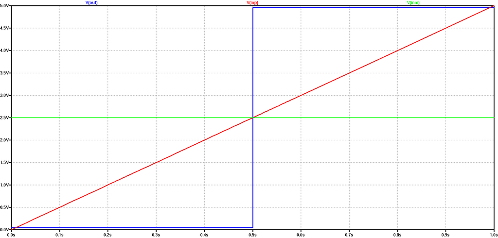
[Out: BLU ; -In: GRN ; +In: RED]
The comparator has a 1V LSB. With input of zero, the output code is 000. As the input level increases, the output code remains at 000 until the transition point at +½LSB is reached. At the (ideal) transition point, the error is zero and the process repeats. The transition error ranges from +½ LSB to –½ LSB.
Consider an input of 750 mV; the output is 1V. The difference between the input and output is 250 mV. This difference is quantization noise. This noise (assuming a range of ±½LSB) may be expressed in the form:

This noise is random with a rectangular probability distribution over the range of ±½LSB.

where:
![]()
If the full-scale range (FSR) is 1.0 V, then:
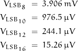
An 8-bit converter adds rms quantization noise of 0.289 /256 , or about 1/890 of FSR (about 1.12 mV for 1V FSR where 1 LSB is about 3.9 mV). A 12-bit converter adds 0.289 /4096 or about 1 /14,200 FSR (70 ![]() V) and a 16 bit converter adds: 0.289 /65536: 1 /227,000 or about 4.4
V) and a 16 bit converter adds: 0.289 /65536: 1 /227,000 or about 4.4 ![]() V where 1 LSB is 15.3
V where 1 LSB is 15.3 ![]() V.
V.
Consider an ADC input signal having an amplitude of 1.0 volt with rms noise of 1.0 mV. Ideally, a 1.0 volt input becomes the digital number 255. The noise component would then be 0.255 LSB. The addition of QE would bring the total noise to √[0.255^2 + 0.289^2] or about 0.385 LSB (~1.5 mV).
While this is a significant increase of noise over that in the analog signal, the noise alone would not change the digital word as both values are less than the available resolution of the converter (1 LSB = 3.9 mV) but it would limit the range of noise-less signal from (1 – 0.255) LSB to (1 – 0.385) LSB to be represented by that bit.
SNR, DR, and Bits
The number of bits required in a system for an “accurate” representation of the input is dependent on both the uncertainty present at the input and the allowable error tolerance of the output. This is quantified with the ratio of “signal” to “noise” – the signal-to-noise ratio (SNR).
If the input signal is random with a uniform distribution over the full-scale range and the quantization error is also a random distribution over a range of 1 LSB, the SNR is found to be:

Recalling that ![]() and defining
and defining ![]() :
:

Conversely, the number of bits required to represent the signal with noise is found from:
![]()
The ![]() of a 12-bit ADC with full-scale input is therefore:
of a 12-bit ADC with full-scale input is therefore:
![]()
and for 16-bits:
![]()
Common usage of the term “SNR” can cause confusion; it often implies “dynamic range” (DR) – the ratio of maximum to minimum signal; the minimum signal is often defined by the noise floor in which case the terms are synonymous – but the terms themselves have slightly different meanings![]() .
.
While one means of determining this ratio involves defining the RMS value of a signal sine wave; it is best to recall that the basic ADC “sees” a sequence of DC values; values which are constant during the conversion time (via a sample/hold network).

Recalling that an RMS voltage is equivalent to a DC voltage, the maximum SNR in the absence of all perturbations except QE can be calculated as:

For a 12-bit converter:
![]()
An alternative definition of SNR – assuming a Gaussian distribution of magnitudes and only positive values – defines the ratio of mean to standard deviation such that:
![]()
where ![]() is the expected value (mean) and
is the expected value (mean) and ![]() is the standard deviation of the noise. This definition is simply defines an alternative symbology: the “ideal” signal is the mean; the standard deviation of noise described by a normal distribution is the RMS value. And the range of values between
is the standard deviation of the noise. This definition is simply defines an alternative symbology: the “ideal” signal is the mean; the standard deviation of noise described by a normal distribution is the RMS value. And the range of values between ![]() 3
3 ![]() includes 997/1000 of probable magnitudes … for a function fitting the ideal (I personally like to add about 10% to the calculated rms noise value calculated in this manner).
includes 997/1000 of probable magnitudes … for a function fitting the ideal (I personally like to add about 10% to the calculated rms noise value calculated in this manner).
NOTE:
With quantization noise having a peak-to-peak amplitude of 1 LSB and no signal, the maximum SNR equals the maximum dynamic range as 20 log 2^N or about 6.02 N. If I define an n-bit floating point number with m bits representing the exponent, the mantissa is allocated n-m bits so that dynamic range is now DR = 6.02 2^m and SNR is 6.02 (n-m)
That’s good for now.

1SNR and DR mean the same thing when the noise floor is considered the minimum signal. It is often good practice to have the minimum signal be 20 dB or so above the noise floor in which case the DR would be 20 dB less than SNR.