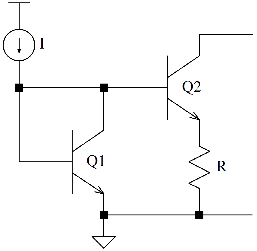
The National Semiconductor LM134 (now TI) is basically a bipolar Modified Widlar Mirror topology intended for use as a discrete current source with an adjustable output range of 1 uA to 10 mA. It has 3% initial accuracy and operates over the temperature range of -55 to 125C. The LM134 in a TO-206 can costs about $10.65 ea.

The output current is determined by the value of the (external) resistor R.
The nature of the device design is such that a separate discrete temperature-sensing diode can be eliminated; the LM134 has a positive and linear temperature coefficient of current which may be used to generate a voltage across a resistance. This resistance should be a low-tempco device. For example, Vishay offers 0.02%, 5 ppm/C resistors (PLTT) in values between 50 and 3 M![]() . Some values are available from DigiKey for about $10-$11 ea. Precision isn’t cheap.
. Some values are available from DigiKey for about $10-$11 ea. Precision isn’t cheap.
One issue with this device is the initial error. The advantage is that it’s a linear slope error – fairly easily corrected . The disadvantage is that the labset procedure to calibrate requires “tweaking” of the effective resistance value. The PLTT resistors have good characteristics but the necessary tweaks could be problemsome to implement.
I’ll pretend I didn’t hear that last.
The nominal output current is:
![]()
with a temperature dependency defined as:
![]()
The output is sensitive to self-heating. Recall that the specification of 25![]() C is for junction temperature, not ambient temperature.
C is for junction temperature, not ambient temperature.
Assuming the TO-46 metal can package …

The current needs to be forced across a (constant) resistor to generate the desired temperature-dependent voltage.
The LM134 will be driven by the LT1236 voltage reference. The ADC REFIN will take about 1.5 mA; the LM134 will be set to something less than 100 ![]() A. The data sheet of the AD7880 suggests that VREF be connected to VDD. The AD7880 requires about 7.5 mA; the LT1236 is rated to source up to 10 mA – so far, this design starts to approach the limits of the LT1236; it will be assumed acceptable for now.
A. The data sheet of the AD7880 suggests that VREF be connected to VDD. The AD7880 requires about 7.5 mA; the LT1236 is rated to source up to 10 mA – so far, this design starts to approach the limits of the LT1236; it will be assumed acceptable for now.
The expression for the temperature-dependent output voltage can be derived as:
![Rendered by QuickLaTeX.com \begin{displaymath} V_{\text{out}} \; = \; \frac{\, R_{\text{load}} \, }{R_{\text{set}}} \, \frac{ \; \left( \, 1 \, + \, \frac{\, \text{tolerance \%} \, }{100} \, \right) \times \left[ \, 1 \, + \, ( \, 25 \, - \, T \, ) \, \text{TC}_{R_{\text{load}}} \right] \; }{ \; \left( \, 1 \, + \, \frac{\, \text{tolerance \%} \, }{100} \, \right) \times \left[ \, 1 \, + \, ( \, 25 \, - \, T \, ) \, \text{TC}_{R_{\text{set}}} \right] \; } \; 0.0677 \,\left[ \, 1 \, + \, ( \, 25 \, - \, T \, ) \, 0.00336 \right] \end{displaymath}](https://davemcglone.com/wp-content/ql-cache/quicklatex.com-394e2bb68242f6daa9bd746c647cc630_l3.png)
If R![]() and R
and R![]() are matched, then:
are matched, then:
![]()
The tolerance and tempcos of the resistor ratio cancel (to get picky … which is part of the point – a mismatch variation may need to be considered). Since the REF source is applied to the sensor and ADC, variations should cancel.
![]()
The slope of ΔV/ΔT is adjusted by the ratio of the set and load resistances but will be on the order of 10s mV/°C. The value of the load resistance should be such that the voltage across the LM134 is greater than 1 V.
Consider also the resulting voltage range. The LM134 data sheet suggests R![]() = 230 and R
= 230 and R![]() = 10k to obtain a temperature coefficient of 10 mV/C … but the resulting voltage range for T = -40 to 125C is 5.50 to 6.15 V … either extreme is out of range
= 10k to obtain a temperature coefficient of 10 mV/C … but the resulting voltage range for T = -40 to 125C is 5.50 to 6.15 V … either extreme is out of range
Each bit of the ADC is equivalent to:
![]()
That’s good for now.
![]()