The creation of a vortex ![]() field forces a redistribution of charge within conductive regions. If an anomaly is placed within the influence of this field, a secondary electric field within the conductor causes charge accumulation at the interface surfaces normal to the applied electric field. The secondary field consists of two components; an electrostatic field created by charge accumulation, and an inductive field created by the time-variant magnetic field as expressed by
field forces a redistribution of charge within conductive regions. If an anomaly is placed within the influence of this field, a secondary electric field within the conductor causes charge accumulation at the interface surfaces normal to the applied electric field. The secondary field consists of two components; an electrostatic field created by charge accumulation, and an inductive field created by the time-variant magnetic field as expressed by ![]() . The secondary field is equal and opposite to the primary field, resulting in zero net electric field within the conductor.
. The secondary field is equal and opposite to the primary field, resulting in zero net electric field within the conductor.
There is an inter-dependency between these fields: the secondary field due to surface charges influences the direction of current flow, and the density of charge is dependent on the primary vortex electric field which causes the redistribution of those charges.
The charge density at some point on a conductive body is expressed as:
![]()
where ![]() is the average value of the normal components of the total field on both sides of the interface near point P. The shift of charge changes the current density thereby creating a secondary magnetic field as defined by the Biot-Savart Law[1].
is the average value of the normal components of the total field on both sides of the interface near point P. The shift of charge changes the current density thereby creating a secondary magnetic field as defined by the Biot-Savart Law[1].
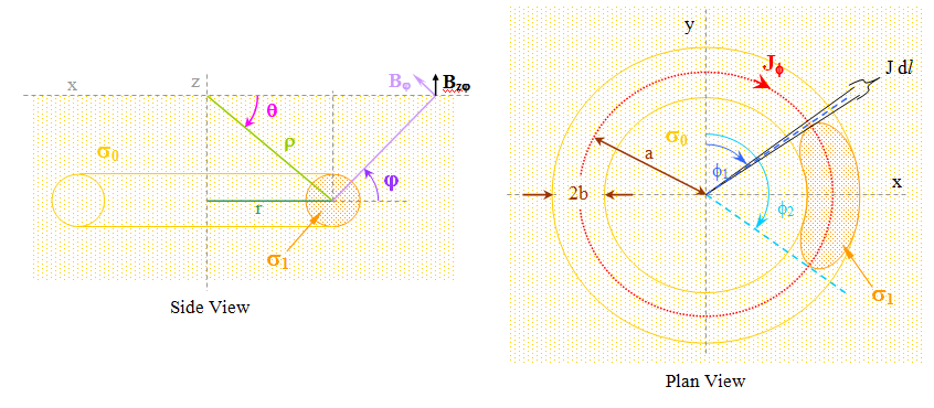
An anomalous conductive body will be defined along a concentric path at radius r from the dipole axis and at some depth z below the surface. The target will be an ellipsoidal body as shown:

The location of the target will be defined as shown. The magnetic dipole will cause a radial electric field. This field will intersect the conductive body causing charge movement – a current which creates a secondary magnetic field. This magnetic field will distort the primary field. This distortion will modify the measured surface magnitude.
The geometrical description of the ellipsoid is defined as eccentricity, e:
![]()
where α is the major axis radius and β is the minor axis radius.
The major axis is coincident with the current flux. A flux toroid is defined so that its radius equals that of the ellipsoidal minor axis (β) while the major axis (α) has a length equal to an arc segment of the toroid.
A simplifying assumption is made that the degree of curvature of an arc segment along unit vector ![]() is small and may be approximated by a straight line, and that J × dS is constant throughout the tube.
is small and may be approximated by a straight line, and that J × dS is constant throughout the tube.
In order to find the field solutions, the boundary conditions need to be determined. The Laplace Equation defining the electric field potential requires 1st order Legendre functions of the 1st and 2nd kind.
The solution coefficients are found to be:
![Rendered by QuickLaTeX.com \begin{displaymath} A \; = \; \dfrac{\left(\, \dfrac{\gamma_i}{\gamma_e} \, - \, 1 \, \right) \, \alpha \, \beta^2}{\, c^3 \, \left[ \, 1 \, + \, G \, \left(\, \dfrac{\gamma_i}{\gamma_e} \, - \, 1 \, \right) \, \right] \, } \qquad B \; = \; \dfrac{1}{\, 1 \, + \, G \, \left(\, \dfrac{\gamma_i}{\gamma_e} \, - \, 1 \, \right) \, } \end{displaymath}](https://davemcglone.com/wp-content/ql-cache/quicklatex.com-6a31753cbb3539cb3e2d3da12be12ee7_l3.png)
where:
![]()
Function ![]() characterizes the effect of current density such that:
characterizes the effect of current density such that:

The secondary magnetic field which arises from this current is found through:
![]()
where ![]() is the sum of the primary and secondary fluxes forming the total current.
is the sum of the primary and secondary fluxes forming the total current.
A little bit of algebra provides an expression for the total current:
![]()
Combining the previous two expressions gives:
![]()
The vertical component of this secondary field will manifest itself at the surface as:
![]()
… keeping in mind that the actual field that is measured contains components of the primary field as well as other fields and distortions that will be present in an actual measurement environment.
The electromotive force may be defined as a function of current flux:
![]()
where ![]() represents the effective resistance of a toroidal segment of conductive material.
represents the effective resistance of a toroidal segment of conductive material.
![]()
The current density within the conductive segment is found to be:
![]()
which leads to an expression for current:
![]()
The inductance L associated with a toroidal current volume may be determined as[2]:
![]()
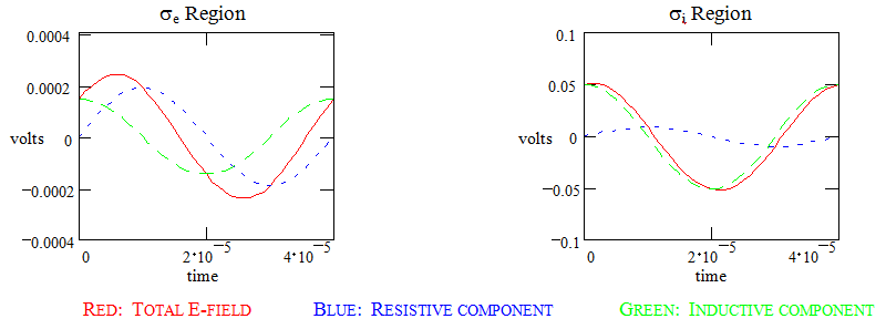
Let’s consider what happens with the fields within a couple of fairly non-conductive materials. I’ll use a dolomite having conductivity of ![]() within a sandstone having conductivity of
within a sandstone having conductivity of ![]()

The external E field only changes by ![]() 250 μV – difficult to detect on the surface but the target is not one of a desired conductive region (such as a metal-bearing ore zone).
250 μV – difficult to detect on the surface but the target is not one of a desired conductive region (such as a metal-bearing ore zone).
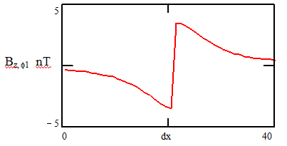
The mapping of the ![]() -field is more encouraging:
-field is more encouraging:

The absolute magnitude swing is ![]() 4 nT – well in excess of the minimum detectable signal of 0.05 – 0.1 nT.
4 nT – well in excess of the minimum detectable signal of 0.05 – 0.1 nT.
All looks well to here, so …
That’s good for now.
![]()